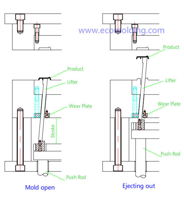
1. The lifter is mainly used to form the internal undercuts of a molded plastic part, and at the same time it also offers ejection function. The mechanism features a simple structure but poor rigidity and a short travel distance. The typical structure is shown as below:
- Most injection mold company usually apply the lifter structure as shown . The lifter employs the 8407 steel with a hardness of up to HRC50-52. There should be a distance of 1 – 3mm from the angle lifer to the product, with a clearance of 0.1mm on each side of the base made of the 738 steel, while the length tolerance is +1.5mm and +1.0mm on the top and bottom respectively.
- At the end close to the melt flow, a 5.0mm plane surface has to be made (unnecessary when the part profile surface is plane), as well as a head that is bigger than (if not equivalent to) 1.0mm, to prevent the angle lifter from being moved by pressure during the injection molding process. A C0.2 chamfer needs to be set up on the mold core at the corner of the head.
- The top of the lifter needs to be 0.03 – 0.05mm higher than the part profile surface, so as to avoid scratch during ejection.
Made of bronze, the wear block adopts the integral form and is installed under the B plate, with the main purpose to avoid lifter deformation and locate the angle lifter during the ejection process. The ejector retainer plate needs to be equipped with a limit column, which should be higher than the lifter base. When ordering a mold base for a injection mold designed with lifters, the spacer block needs to be higher, considering the travel distance of the angle lifter, so as to prevent insufficient travel distance.