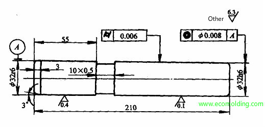
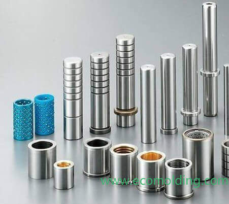
There are many types of guide pin structures in plastic injection mold application, among which the standard structural design is shown in the figure below. A guide pin has to serve as the cylindrical surface of concentric circles of different diameters. Based on structural dimensions and material requirements, a round steel bar with an appropriate size can be directly selected as the material. In addition, the technical requirements of guide pins need to be satisfied during the machining process.

Fig. 8-2 Structural Shape of a Guide Pin
Technical Requirements of Guide Pins
(1) At the joint between the guide pin and the fixed mold plate, the diameter concentricity tolerance should not exceed 1/2 of the diameter tolerance in the working portion.
(2) The cylindricity tolerance of the guide pin in the working portion should be kept within requirements.
(3) After being machined, the precision, surface quality and thermal treatment of each part of the guide pin should meet the requirements specified in the drawing. When applicable, the carburized layer on the working surface is required to be uniform usually with a thickness of 0.8 – 1.2mm.
Machining Process of Guide Pins
(1) Material Preparation & Cutting. The commonly used material of the guide pin is the 20 steel (or select materials as per the drawing). After cutting, an allowance of 3 – 5mm should be retained for facing; and an allowance of 3 – 4mm for cylindrical turning.
(2) Facing & Centering. Turn one end, retain a turning allowance of 1.5 – 2.5 mm, and drill the centered hole; turn the other end to specific dimensional requirements and drill the centered hole.
(3) Cylindrical Turning. Roughly turn the cylinder, and retain an allowance of 0.5mm on each side for grinding. When applicable, groove the guide pin to specification.
(4) Inspection. Inspect the finish sizes of the previous steps.
(5) Thermal Treatment. Follow the process, and ensure a carburization thickness of 0.8 – 1.2mm. After carburization, the quenching hardness is 58 – 62HRC.
(6) Lapping. Lap the centered hole on one end, and then lap the one on the other end.
(7) Grinding. Apply cylindrical grinder and centerless grinder to grind the cylinder. After grinding, an allowance of 0.01 – 0.05mm should be retained for lapping.
(8) Lapping. After machining, the surface of the cylinder needs to be lapped to reduce surface roughness, thus meeting the surface finish requirements.
(9) Inspection. Inspect the finish size of each step.
