PMMA acrylic injection Molding Defect Causes and Solutions

PMMA acrylic injection molding

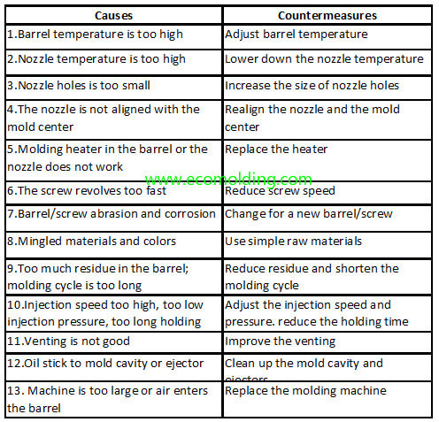
The defects in the injection molding of acrylic PMMA usually include: short shot, silver streaks, sink marks, voids, jetting, weld marks, gray / black specks, cracking, warpage, and material impurity, while the preventive measures against them are usually:

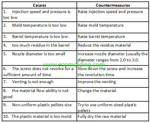
Short Shot

This is caused because the resin does not fill the cavity fully. To prevent its occurrence, we can take the following measures:

1. Adjust the supply quantity of acrylic pellets

2. Increase the injection pressure

3. Increase the injection speed

4. Raise the barrel temperature

5. Increase the screw backpressure

6. Raise the mold temperature for molding of thin-walled products

7. Extend the pressure holding time during injection

8. Extend the molding cycle

9. Increase the cross-sectional area of the gate (main runner, branch runner, and feed port) and reduce its length, to allow the resin to flow more easily.

Silver Streaks

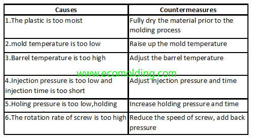
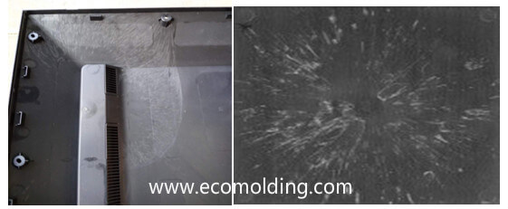
These are the silver-white streaks on the product surface which are generated in the feed port along the flow direction of the resin. Caused by multifaceted factors, silver streaks can be prevented by taking the following measures:

1. Fully dry PMMA acrylic pellets

2. Reduce the barrel temperature and increase the injection pressure

3. Increase the injection speed

4. Reduce the screw speed and adjust the backpressure

5. Increase the mold temperature and reduce the barrel temperature for injection molding of thin-walled products

6. Determine the time duration of the molten state

7. Increase the cross-sectional area of the gate (main runner, branch runner, and feed port) and reduce its length, to allow the resin to flow more easily and reduce the barrel temperature.

Voids

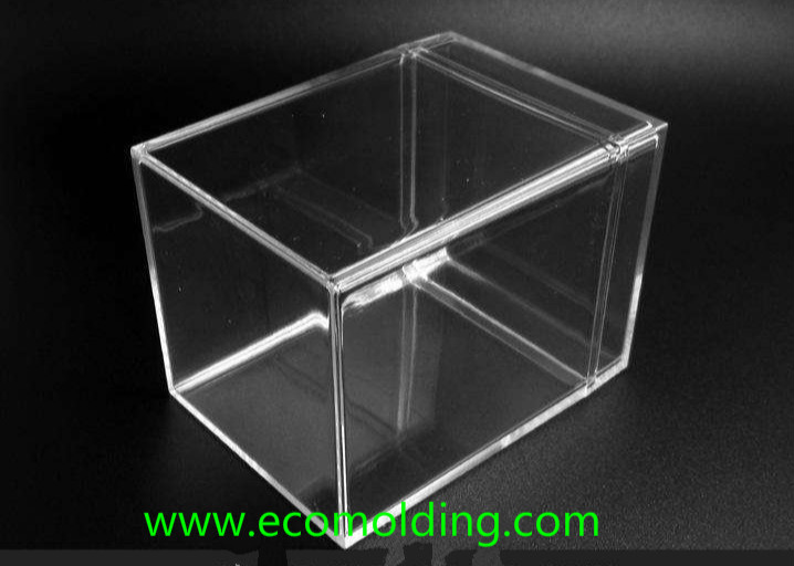
These are the voids that occur where the product wall is thick. For transparent PMMA products, they will become an exterior defect that cannot be remedied later. Insufficient drying before molding or excessive barrel temperature may cause voids to occur in areas other than the center of the thick wall. If the shrinkage is concentrated in the thick wall, voids will appear in the center of the thick wall. It can be solved by the prevention of shrinkage, or by the following measures:

1. When cooled with water after ejection, increase the temperature of the cooling water or reduce the water-cooling time

2. Raise the mold temperature

Jetting

These are the ring-shaped stripes that occur on the surface of a product and are centered around the feed port. It can be prevented by taking the following measures:

1. Raise the barrel temperature

2. Raise the mold temperature

3. Increase the injection pressure and injection speed, so that it fills the cavity more quickly

4. Extend the molding cycle

5. Increase the cross-sectional area of the gate (main runner, branch runner, and feed port), and reduce its length, to allow the resin to flow more easily

Cracking / Crazing

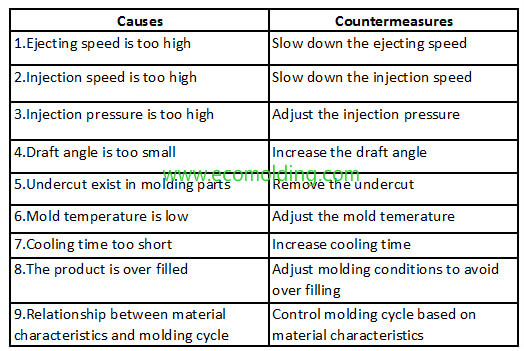
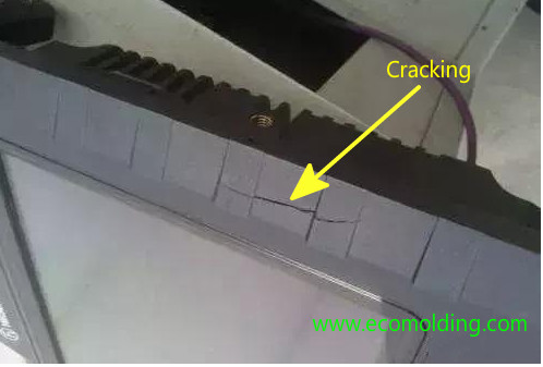
These are the cracks that occur on the surface or the contact surface with the insert of a product. When viewed from a certain angle, it will flicker and emit light. The causes of this defect are relatively complicated, which, however, can be prevented by taking the following measures:

1. Increase the barrel temperature

2. Increase the mold temperature

3. Increase the injection speed

4. Adjust the injection pressure

Material Impurity

PMMA acrylic are widely used in all aspects of the optical field, so it is extremely necessary to prevent the mixing of impurities. Usually, there are many ways for foreign substances to be mixed in. It is time-consuming to find out the reason, but you can start with the following aspects:

1. What is the amount of dust suspended in the molding factory

2. Is the operation messy when unpacking the acrylic pellets?

3. Are there any other resins mixed in the pre-dryer, or are there any foreign substances caused by friction between the dryer and the receiver?

4. Is the hopper loader thoroughly cleaned?

5. Does the strong friction between the metal wall of the hopper loader and the acrylic pellets cause the metal wall to peel off?

6. Is there any soot or dust mixed in from the vents of the hopper loader, or whether there are foreign substances generated by the hopper loader itself?

7. Are there traces of other resins in the barrel or nozzle?

8. Is there any friction between the barrel and the screw?

9. Is there any oil or metal powder generated at the ejector pin or other friction parts of the mold?

Plastic annealing and Moisture conditioning process for plastic product

Plastic annealing process

Plastic annealing process

The purpose of plastic annealing is to eliminate internal stress. For example, in the area where the thin and thick parts meet, the cooling of the thick part is slower than that of the thin part, causing the joint to shrink unevenly. As a result, there is stress concentration in the area. This phenomenon is more obvious around metal inserts. If annealing is not performed, cracking or even deformation may occur in the stress concentration area after a period of time. Annealing method: Usually, the product is immersed in hot oil, hot water, or cycling hot air. The annealing temperature is adjusted according to the type of the plastic, but usually, it is 10-20°C lower than the product’s thermal deformation temperature, or the product will deform. However, the temperature should not be too low either, or the desired effect will not be achieved.

Annealing conditions for several common plastics are shown in the table below:

Plastic Agent Temperature (°C) Product Thickness (mm) Time
(min)
Nylon Oil 130 12 15
ABS   80-100   16-20
PC Air 125-130 1 30-40
PE Water 100 >6 60
PP Air 150 <6 15-30
PS Air or Water 60-70 <6 30-60
PSU Air or Water 160 <6 60-180

Moisture Conditioning of Plastic Products

Moisture conditioning of plastic products is mainly for polyamide (nylon) products. After storage for a period of time, products made from this raw material will deform and expand due to absorption of moisture in the air, thus resulting in size change. Therefore, after a nylon product is molded, it should first be immersed in 100-120°C water or potassium acetate solution, to keep it isolated from the air. The immersion time is determined according to the wall thickness and the shape of the product. Then, take the product out after the temperature is slowly lowered to the room temperature.

What causes ejector pin marks in injection molded parts?

Ejector pin marks usually refer to the glossy or white imprints on the surface of a injection molded product, as well as the different levels of glossiness – dark or shadow, without convex or concave – visible directly opposite to the ejector pin location.

ejector pin marks

Factors that cause ejector pin mark 

1. Product design: 

Inappropriate product design:

1). The thickness of a product is an important factor to consider during structural design. Increasing the thickness of a product is able to not only improve the filling performance of the resin, but also reduce the orientation stress as well as product deformation. On the contrary, the excessively thin wall will make it difficult to fill the cavity, and accordingly require the increase of various molding parameters, thus making it easy to generate ejector pin marks.
2. Mold design: 

1). Inappropriate gating system design: the runner is too narrow, the main runner is too long, or the runner is designed with sharp turns. All these factors will increase the flow resistance, greatly limits the filling of the plastic, and affects the adjustment of the molding parameters.

2). Inappropriate gate design: the type, location, size, and number of the gate. If the gate is too small, too much flow resistance and orientation stress will be caused. The internal stress around the gate is the highest, making the area more severely affected by stress.

3). Inappropriate ejector mechanism design: the ejector type, size, location and quantity all influence the occurrence of ejector marks, such as ribs, flanges, and bevels on plastic parts.

4). Inappropriate mold cooling channel design: the product is not evenly cooled in the cavity.

5). Inappropriate mold venting system design: when the product is in a vacuum in the cavity.

3. Machine parameters:

1). Inappropriate injection parameters: control of injection pressure and injection speed, as well as the selection of injection switching position.

2). Inappropriate holding pressure parameters: control of holding pressure and holding pressure speed, selection of holding pressure switching position, and level of backpressure.

3). Inappropriate mold temperature parameters: the different temperature settings of the mold core and the mold cavity, and the corresponding cooling channel selection for the product.

4). Inappropriate material temperature parameters: the temperature settings for each section of the barrel.

5). Inappropriate ejection parameters: the influence of ejection speed, pressure and type.

6). Inappropriate clamping force parameters: selection of machine tonnage and setting of clamping force.

Causes of ejector pin marks and solutions 

1. Product design: 

Whether the product wall thickness is appropriately designed is dependent on the raw material and product structure. Usually, the thickness of a simple-structured product needs to be no less than 2.5mm. Comparatively speaking, for some complex-structured products, i.e., products with more ribs in the cavity, the thickness must be no less than 2.8mm.

2. Mold design: 

1). In order to save raw materials and facilitate subsequent mold changes, the sizes of the nozzle and runner are usually not too large when they are first designed. When ejector marks occur on the product, the sizes of the sprue and the runner can be appropriately increased to alleviate the overshooting of the injection pressure and other parameters caused by filling difficulty (note: the sizes of the sprue and the runner can only be changed and increased when the injection parameters are too high, or other severe issues may occur; design vents at the runner end). The internal stress around the gate is the highest, so the gate should be located where it is easy to fill the cavity and as far away as possible from the ejector, while resin filling should be as uniform as possible to ensure uniform stress distribution.

2). The type, arrangement, size, location and number of ejectors all have a lot to do with the occurrence of ejector marks. The design should ensure that the properly sized ejector pin is uniformly stressed when the product is ejected. For example, the areas with deep ribs, that is, the areas where it is more difficult to eject the product, need to be ejected with higher force. Also, the ejector pins need to be designed on the ribs.

For products with deep ribs, it is necessary to put the stress points on those deep ribs, so as to avoid ejector marks caused by excessive force during product ejection.

The design of the ejector pin location should take the following two factors into consideration: whether it is ejected at the maximum stress point and whether it is balanced.

ejector pins location

3. Machine parameters: 

1). Selection of injection molding machine: Inappropriate selection of injection molding machine will also lead to the generation of internal stress. The idea that a large-capacity injection machine injects products with a small mold will reduce internal stress is incorrect. Sometimes large internal stress is caused by excessive pressure and inappropriate nozzle structure.

2). Molding process conditions: Due to the characteristics of the molding process, ejector marks are inevitable on molded products, but the appropriate control of process conditions is able to minimize them; the factors that influence the occurrence of ejector marks include mold temperature, processing temperature, injection speed, injection pressure, holding pressure, injection time, pressure holding time, and cooling time, etc., among which, temperature, pressure, speed and time constitute the main factors of the plastic injection molding process.

3). Processing temperature

4). Injection pressure, speed and time

5). Holding pressure and holding time: For holding pressure, when the product is more than 90% injected, use this parameter to adjust it. Sometimes, reducing the holding pressure and the holding time is able to reduce the orientation stress. At this point of time, you will find that ejector marks are actually much improved.

6). Insufficient cooling time. When the product is ejected before its surface temperature reaches the highest ejection temperature of the plastic material, ejection defects such as convex or penetration are prone to occur.

What causes cracking in plastic injection molded parts

cracking injection molding defects

Cracking is a commonly seen defect in plastic injection molded products, of which the main causes are stress and deformation, mainly including residual stress, external stress and product deformation caused by external environment.
(I) Cracking caused by residue stress
The residual stress is mainly generated in the following three scenarios, i.e., overfilling, product ejection and metal inserts. The cracking generated in the case of overfilling can be solved from the following aspects:
(1) Since the direct gate is able to minimize pressure loss, if cracking is mainly generated around the direct gate, you can opt for the multi-point gate, the side gate or the tab gate.
(2) On condition that the resin material does not decompose or deteriorate, appropriately increasing the resin temperature is able to reduce melt viscosity and improve fluidity, while reducing the injection pressure, so as to lower the stress.
(3) Usually, stress easily occurs when mold temperature is low, so the temperature should be appropriately increased. However, when the injection speed is high enough, stress can also be reduced even though the mold temperature is relatively low.
(4) Stress will also occur when the injection and pressure holding time is too long. It would be better to reduce the time or perform pressure switch appropriately.
(5) It should be noted that amorphous resins, such as AS, ABS and PMMA, are more prone to residual stress than crystalline resins, such as PE and POM.
During product ejection, stress is generated due to the high ejection force caused by the small draft angle, rough mold core / cavity. Sometimes, even ejector marks or cracking occurs around the ejector pin. Just look closely at the location of cracking to identify the cause.
Stress is the most likely to occur when metal inserts are involved in the plastic injection molding process. And, the cracking usually occurs after a period of time, so it is extremely harmful. The stress is mainly caused by the large difference in thermal expansion coefficient between the metal and the resin materials. As time goes by, the stress exceeds the strength of the resin material that gradually deteriorates, so cracking occurs. In order to prevent the cracking thus caused, as a rule of thumb, the general-purpose PS is basically not suitable for inserts, while the impact of the inserts on the nylon material is minimal. Thanks to the small thermal expansion coefficient, the glass fiber reinforced resin is more suitable for the application of inserts.
In addition, a better effect can be achieved if you pre-heat the metal insert before injection molding.
(II) Cracking caused by external stress
The external stress mainly refers to the stress concentration caused by inappropriate design, especially the sharp corners.
(III) Cracking caused by external environment
Chemicals, water degradation caused by moisture absorption, and excessive application of recycled materials will degrade the physical properties, and thus cause crackin

What causes black specks/black streaks in injection molding parts?

black specks streaks

Black specks/streaks and impurities are the most important factors that lead to rejects in the normal production process. It mainly affects the appearance of the product and leads to scrap. Most of the impurities and black specks are usually caused by foreign substances, i.e., they have nothing to do with the raw material itself. Only a small portion of the black specks and impurities are caused by the raw material itself.
  

Black specks and impurities are characterized by small dark brown particles, which generally do not reflect light. When the particles are large, the impurities are layered, brittle, fragile and porous after being broken. Some of them are irregularly scattered on the whole, some are scattered randomly in local parts, and some only occasionally appear in a local area.

Impurities are divided into two major categories, the ones formed before and during the molding process:

Black Specks & Impurities Formed before Molding:

1. Due to various reasons, foreign substances are not cleaned during the processing of the raw material, leading to black specks on the raw material;

2. Impure granulation causes black specks;

3. The raw material is mixed with color masterbatch or speckled crushed blocks and scraps;

4. Impure material – low melting-point material is mixed with high melting-point material;

5. Impurities may be mixed in during packaging, transportation and storage, of which, the obvious feature is that after the raw materials are unpacked, you can see that there are foreign matters and impurities on the surface of the material pellets if you observe carefully;

6. Impurities and foreign substances during material feeding;     

7. Carbonization of raw materials

With regard to carbonization of raw materials, the black specks are generally larger in volume, and the largest ones may reach 1-2mm in diameter. Most of the “black specks” are thicker, but there are also thinner ones consisting of one or two layers. This is usually caused by long-term raw material storage, or that the raw material is locally overheated, leading to decomposition, coking, and carbonization into agglomerates. It is formed after the material is crushed by shearing when flowing through the screw or the nozzle.

Causes of Material Carbonization:

1. The melt temperature is too high. If the temperature of the material is too high, it will cause decomposition and form carbides. Especially for some heat-sensitive materials with a very narrow temperature range, the temperature of the barrel must be kept moderate.

2. Material coking: If the molten plastic stays in a certain place for too long a time, coking will occur, thus causing black speck. The areas that may cause material retention include joints between the nozzle and the barrel, the barrel wall, the melt ring, the connection between the nozzle and the gate, the corner of the hot runner, and the dead corner in the sprue, etc.

3. The barrel clearance is too large – the gap between the barrel and the screw is too large, which will cause the material to stay in the barrel, and the retained material will decompose after long-term overheating, thus leading to black specks.

4. Additives discolor due to degradation and decomposition. Additives include antistatic agents, violet / infrared absorbers and general dyes. Their properties are generally more active than the raw material. Under the action of the shearing force at the processing temperature, they have already been decomposed into dark, brown, and even black colors, presented as black specks and impurities after plastic injection molding.

Black specks and impurities due to external causes are very common in production, and they are very stubborn after occurring.

1. The mold material is not good, with iron powders falling off the parting surface, the molding surface or the kiss-off surface, thus causing black specks.

2. The ejector pin is rough and easy to burn, causing iron powders to fall off and thereby the black specks.

3. The slider generates iron powders, leading to black speck.

4. The slider rusts or generates other stains due to water leakage inside the slider, which are thrown out by slider movement, and black speck are caused when they fall onto the product.

Distinguish the Black Specks:

If the black speck appear on both the entire product surface and in the depth of the part, they should be formed before injection molding; if the black specks only appear on the surface, they should be formed during injection molding. If at the same time they are only distributed in a specific area of the surface, it is undoubtedly that they are black specks formed during the injection molding process; if the black speck are large (generally 0.5- 1mm), it should be caused by material carbonization; if they are also dark, brittle and porous, it can be confirmed that they are caused by carbonization: if the black specks are particularly dense and the raw material is checked for no obvious impurities, it is usually caused because the previous material is not immediately cleaned before the material change, otherwise the material should be looked into to identify the reason.

Solutions:

1. For impurities in a molded product, black specks are caused due to foreign substances mixed in the raw material, so the cleanliness of all the links, including production, packaging, storage, transportation, unpacking, material mixing and the barrel, must be strictly controlled.

2. For black specks caused by carbonization, the injection temperature should be strictly controlled.

3. Usually, for the black speck caused by additive degradation or the ones caused by the existing carbonized materials deposited on the screw surface and the screw barrel wall, they can be removed from the original location into the molten material under various strong shearing effects in the screw barrel during the production process. The “removal” is a process in which black specks and impurities appear in the product. When changing materials or colors, if this impurity “removal” process is inevitable, we must try our best to minimize it, i.e., “cleaning.”

What causes parts sticking or sprue sticking during injection molding?

parts sticking or sprue sticking

The causes of parts sticking and sprue sticking are multifaceted, among which mold failure is one of the main reasons. The reasons and corresponding solutions are described as follows:

1. The surface of the mold cavity and sprue bush is rough. If there are surface defects such as gouges, nicks, scars, and dents in the mold cavity and sprue bush, the plastic parts and sprue will easily stick to the mold, resulting in difficulty in ejection. Therefore, the surface finish of the cavity and sprue should be improved as much as possible. The inner surface of the cavity should preferably be chrome-plated. When polishing, the movement direction of the polishing tool should be the same as the direction of mold filling.

2. The mold wears, is scratched or the insert clearance is too large. When the molten material produces flashing in the scratched part of the mold or in the clearances between the inserts, it can also cause difficulty in product ejection. In response, the damaged mold area should be repaired and the clearances between the inserts reduced. 

3. The mold rigidity is insufficient. If the mold cannot be opened at the beginning of injection, it means that the mold is deformed under injection pressure due to the insufficient rigidity. If the deformation exceeds the elastic limit, the mold cannot return to its original state and thus cannot be used anymore. Even though the deformation does not exceed the elastic limit of the mold, the molten material is cooled and solidified under high conditions in the mold cavity. After the injection pressure is removed and the mold recovers from deformation, the plastic part is clamped by the rebound force, so the mold still cannot be opened.

As a result, when designing the mold, sufficient rigidity and strength must be ensured. When trying the mold, it is the best to install a dial indicator on the mold to check whether the mold cavity and the mold base are deformed during the filling process. During mold trial, the initial injection pressure should not be too high. You should observe the deformation, while slowly increasing the injection pressure, so as to keep the amount of deformation within a certain range.

When mold clamping failure occurs due to the too-high rebound force, it is not enough to increase the mold opening force alone. But instead, the mold should be disassembled immediately, and the plastic part should be heated and softened before being taken out. For molds with insufficient rigidity, a frame can be mounted on the outside of the mold to increase its rigidity. 

4. The draft angle is not big enough, or the parallelism between the core and cavity plates is poor. When designing and making the mold, a sufficient draft angle should be ensured, otherwise it will be difficult to eject the plastic product. Forceful ejection often causes the plastic part to warp, leading to ejection marks or cracks. The core and cavity plates of the mold must be relatively parallel, or it will cause the cavity to deviate, thus resulting in parts sticking. 

5. The design of the gating system is inappropriate. Part sticking and sprue sticking will be caused, when the runner is too long and too small in size, the connection between the main runner and the branch runner is not strong enough, there is no cold slug well in the main runner, the gate is poorly balanced, the diameters of the main runner and the nozzle are not properly matched, or the gate sleeve and the spherical nozzle surface do not match. Therefore, the length and the cross-sectional area of the runner should be appropriately reduced, and the connecting strength between the main runner and the branch runner increased, with a cold slug well provided in the main runner.

When determining the gate location, the filling rate of each cavity in a multi-cavity mold should be balanced and the pressure in each cavity reduced by adding auxiliary gates. In general, the diameter of the small end of the main runner should be 0.5-1mm larger than the nozzle diameter, and the concave radius of the gate sleeve should be 1-2mm larger than the nozzle radius.

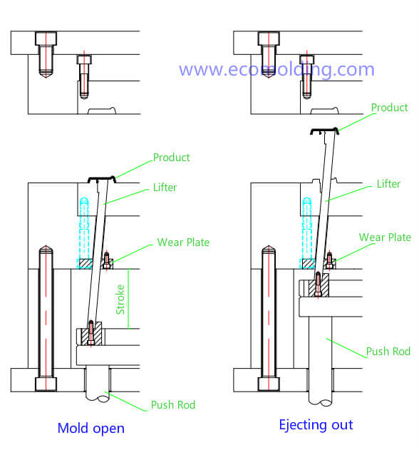
6. The ejection mechanism is not appropriately designed or operated. If insufficient stroke, uneven ejection or poor ejector plate movement occurs to the ejection mechanism, the plastic parts will not be able to be ejected.

When the conditions allow, the effective ejection area should be increased as much as possible to ensure a sufficient ejection stroke. The ejection speed of the plastic part should be kept within a suitable range, neither too fast nor too slow. The main reason for the undesired movement of the ejector plate is the stickiness between the sliders.

What Causes Jetting in Plastic Injection Molding Product?

jetting plastic injection molding defects

Jetting, also known as jet, worm track, or snake-like pattern, refers to the snake-like curves on a plastic injection molded part along the flow direction from the gate, as shown in Figure 1. Under normal circumstances, the molten plastic fills the mold cavity in a “fountain flow” manner, as shown in Figure 2, which depicts the “fountain flow” in detail. However, when the molten plastic flows at a high speed through narrow areas, such as the nozzle, the runner and the gate, and then suddenly enters an open and relatively wider area, the plastic melt will be injected from one end to the other of the cavity in the form of jet streams, creating folded strips. The melt that enters the cavity later fills the remaining space in the mold cavity with a normal fountain flow and is welded to the jetted streams. Since the melt is immediately cooled the moment it makes contact with the cavity wall (mold surface) which has a relatively low temperature, making the temperature of the jetted material lower than that of the fountain stream that comes later, thus causing poor welding and obvious jetting on the surface of the product. Study shows that the root cause of jetting is related to the mold design on the one hand and the viscoelasticity of the material on the other. From the perspective of the mold, when the molten plastic reaches the gate through a larger-sized runner, the flow resistance of the melt is greatly increased because the gate size is usually very small. In order to pass through the gate, the pressure output of the injection molding machine sharply increases. Accordingly, the pressure of the melt increases greatly, and a sizable shrinkage occurs, so when it subsequently enters an open and large-sized mold cavity, the resistance suddenly decreases, the pressure is suddenly released and the volume expanded to generate the jetting. The larger the melt pressure difference before and after entering the gate, the easier it is to form jet streams. The smaller the gate, the greater the pressure, the faster the speed, the greater the energy for the melt to fly out, and the more severe the jetting is. From the perspective of materials, the plastic melt features viscoelasticity. When the polymer melt is extruded through a die, the cross-sectional area of the extrudate is larger than that of the die exit, i.e., die expansion. For the filler material, the addition of fillers such as talc, calcium carbonate, and various glass fibers will greatly reduce the viscoelasticity of the material, so the possibility of jetting of the filler material is greatly increased. In addition, the more the filler material, the more likely it is to cause jetting.

Jetting Solutions in terms of mold design

1) Increase the gate size

2) Change the gate location

3) Change the gate type

Solutions in terms of molding process

1) Adjust the injection speed

2) Adjust the melt temperature

3) Raise the mold temperature

4) Increase the holding pressure

Solutions in terms of material

1) Improve the viscoelasticity of the material. Generally speaking, the greater the viscosity of the material, the lower the fluidity, the stronger the viscoelasticity, and the less likely it is to cause jetting. However, as mentioned above, for the filler materials, increasing the fillers may reduce the viscoelasticity, as well as the fluidity of the melt, thereby making it easier to cause jetting.

2) Reduce the amount of gas in the material. During the blending modification of plastics, the addition of various additives, the shear mixing of the screw, and the handling of small molecules by the equipment all affect the gas content inside. When the gas content is high, it causes a layer of small molecules to be attached to the front edge of the melt, which makes it more difficult to vent the gas generated during jetting. In the worse-case scenario, the front edge of the melt is burnt or cavitated.

What Causes Scratches in Injection Molded Products?

scratches scrape marks injection molding defects

The scratches (scrape marks)on the appearance of an injection molded product usually occur on such deep-cavity products as chargers, routers, and chassis, etc. It is also a particularly common problem during the injection molding process, known as one of the 10 most challenging problems in the mold and injection molding industry. Glossy products, as well as products with textured sides are easily scratched. What on earth has caused it? When it comes to the scratches on the textured surface, the first thing that comes to the mind of an engineer is that the draft angle on the side of the product is not large enough, but why the scratch still exist after the draft angle is increased? So, solving the occurrence of scratches is not just a matter of the draft angle. In fact, it is not so simple at all. Now, let’s thoroughly analyze and solve the problem of surface scratches.

The causes of surface scratches mainly include the following factors:

I. Draft Angle

The key issue with the product is that the draft angle of the product is too small, resulting in scratches on the side of the product. To respond to the different texture requirements on the side of the product, we have already gained relevant experience – apply suitable draft angles for texture surfaces of different specifications. To solve this problem, we must try to avoid it in the early stage of product evaluation. If the customer’s product does not allow a sufficient draft angle, we must consider using other mold mechanisms or other technical means to avoid it.

II. Mold Design

In addition to problems with the product, to avoid scratches, mold design also plays a very important role, so you must consider it carefully. Here are some examples to explain how to avoid product side scratches through mold design.

1.To handle the fillet of the parting surface, product designers often directly put in the fillet when designing the product. In fact, this is an unreasonable design, because the draft angle at the conjunction between the fillet and the surface is close to zero, which is easy to cause scratches.

2. Mold Structure: Improper mold matching design will also cause the core and the cavity to be misaligned during the mold opening process, thus causing product scratches.

3. When designing the mold gate, you should consider the gate design so as not to cause too much pressure on the product and cause side scratches on the product. The gate should be as far away as possible from the textured side surface, because the pressure at the gate is high also with a long pressure holding time, so the high clamping force will make the product to be prone to scratches.

4. The product sticks to the mold cavity: We must ensure that the product 100% sticks to the mold core when the mold is open. If it sticks to the mold cavity, local product warpage may be caused, and thus scratches on the side surface. When necessary, a product fixing structure must be deployed in the mold core to ensure that the product stays with the core.

III. Mold Machining

1. Although the draft angle is designed to be big enough, it is easy to cause errors during mold machining, because it is difficult to measure the angle accurately. This point must be taken into consideration.

2. It is the easiest to create undercut on the side wall of the mold cavity during mold polishing, because the mold polishers are often afraid to polish the parting surface into a fillet. The mold polishing workload close to the bottom is higher and the one close to the parting surface is lower, which is nothing less than reducing the draft angle of the product, so it is also a possible factor that causes product scratches.

IV. Molding Machine Adjustment

1. Excessive injection pressure and holding pressure are also important causes of scratches on product side walls. Excessive injection pressure creates stress that causes product warpage in the mold. The product may be locally pressed on the side wall, so it is easy to scratch the product side surface during mold ejection.

2. Excessive material temperature will also cause the product surface to be easily scratched.

3. Insufficient product cooling is also one of the causes of product scratches.

4. The bulging of the parting surface also easily causes product scratches. The parting surface bulging caused by excessive clamping pressure, too-soft mold material, and resin powder, etc. may also cause the product side surface to be scratched, so the mold parting surface and texture surface must be kept clean.

5. The injection molding machine is aging, so the parallelism between the front and rear plates is poor. The vibration during mold opening may also be one of the factors that cause scratches on the product side surface.

All in all, the main factors that cause scratches on the side wall and textured surface of a product are comprehensively considered above. Only by carefully following the steps one by one can we avoid the troublesome scratches on plastic injection molded products.

What Causes Weld Lines in Plastic Injection Molding Parts?

weld lines plastic injection molding defects

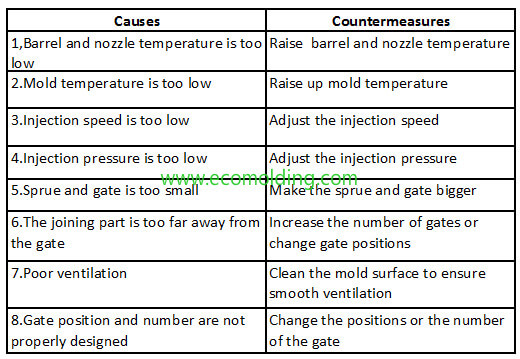
The definition of weld lines: When multiple plastic flow fronts meet in the cavity after encountering inserts, holes, or areas with inconsistent flow rates or interrupted melt flows, or in the case of gate injection filling, the inability of two or more flow fronts to fully “knit” together will cause the linear weld marks. The appearance of weld lines greatly reduces the mechanical strength of the product. The solution to the weld lines is basically the same as the method for reducing product sink marks.

I. Equipment

To respond to poor plasticization and uneven melt temperature, the molding cycle can be extended to make plasticization more complete, and select the molding machine with a higher plasticizing capacity when necessary.

II. Mold

(1) When the mold temperature is too low, raise the mold temperature appropriately or purposefully raise the local temperature at the weld seam.

(2) When the runner is too small, narrow or shallow, and the cold slug well is too small – Increase the dimensions and efficiency of the runner, as well as the volume of the cold slug well.

(3) Increase or reduce the gate section and change the gate location. The gate should be designed to prevent the melt from flowing around the inserts and holes. For the gate where injection filling occurs, we should try to correct, relocate or add a block buffer to it. Try to avoid the application of multiple gates.

(4) Poor venting or no vents. Open, expand or smoothen venting passages, including venting via insert and ejector pin clearances.

III. Molding Process

(1) Increase injection pressure and extend injection time.

(2) Properly adjust the injection speed: a high speed allows the melt reach the meeting point before it is cooled down, while a slow speed allows enough time for the air in the cavity to be vented.

(3) Properly adjust the temperature of the barrel and the nozzle: the higher the temperature, the smaller the viscosity of the plastic, the smoother the flow, and the thinner the weld line is; When the temperature is low, the decomposition of gaseous substances is reduced.

(4) The release agent should be used as little as possible, especially the silicone release agents, otherwise the flow fronts will fail to weld.

(5) Lower the clamping force to facilitate venting.

(6) Increase the screw speed to reduce the viscosity of the plastic; increase the backpressure to improve the density of the plastic.

IV. Raw Material

(1) Dry the raw material and minimize liquid additives in the formulation.

(2) Appropriately add lubricants and stabilizers to the plastic that features a poor fluidity or high heat sensitivity. When necessary, select a plastic that has a better fluidity or higher heat resistance.

V. Product Design

(1) When the wall thickness is small, the part should be thickened to avoid premature solidification.

(2) Make adjustments when the insert is not properly located.

What Causes Burn Marks in Plastic Injection Molding?

burn-marks-injection-molding-defects

Factor 1: Melt fracture causes burn marks

When the melt is injected into a large-sized mold cavity under high-speed and high-pressure conditions, melt fracture will be easily caused. At this point of time, the surface of the melt is laterally fractured, with the fracture area coarsely mixed to form burn marks on the surface of the plastic part. In particular, when a small amount of molten plastic is directly injected into an oversized mold cavity, melt fracture will be more serious, leaving larger burn marks on the product surface.

In essence, melt fracture is caused due to the elastic behavior of the polymer melt. When the melt flows into the barrel, the melt close to the barrel is rubbed by the wall of the barrel, resulting in higher stress and lower melt flow rate. The moment the melt is injected from the nozzle, the stress from the pipe wall disappears. The melt flow rate in the center of the barrel is extremely high, so the melt close to the wall of the barrel is accelerated by the melt in the center. Since the flow of the melt is relatively continuous, the melt flow velocity in the center and close to the wall will be rearranged, tending to the average speed.

During this process, a sharp stress change in the melt will cause strain. Since the injection speed is extremely fast, the stress is particularly high, much higher than the strain capacity of the melt, thus resulting in melt fracture.

When the melt encounters a sudden shape change in the runner, such as diameter shrinkage, expansion, and dead angle, the melt stays and circulates at the dead corner, so its stress is different from that of the normal melt, leading to larger shear deformation. When injected after being mixed with the normal flow, the recovery after deformation of the two is inconsistent and cannot be bridged. If the disparity is large, the fracture will be caused, i.e., melt fracture.

So, it is necessary to solve the melt fracture to eliminate burn marks:

  1. Eliminate the dead angle in the runner and make it as streamlined as possible;
  2. Appropriately raise the material temperature, reduce the melt relaxation time, and make it easy to recover from deformation and bridge the inconsistency;
  3. Add low molecular-weight polymers to the raw material, because the lower the molecular weight of the melt, the wider the distribution, and the more helpful to reduce the elastic effect;
  4. Properly control the injection and the screw speeds;
  5. It is very important to select the gate location and the gate type reasonably. It is proved that the enlarged pinpoint gate and the submarine gate (tunnel gate) are the ideal choices. With regard to gate location, it is preferable to ensure that the molten material is first injected into a transition cavity and then the large-sized cavity. Do not allow the melt to flow into the large cavity directly.

Factor 2: Molding conditions are not appropriately controlled

This is another important cause of charring and burns marks on the surface of a plastic product. In particular, the injection speed has a great influence on it. When the melt is slowly injected into the cavity, the flow state of the melt is laminar; when the injection speed gradually increases to a certain value, the flow state gradually becomes turbulent.

Generally speaking, the surface of the plastic part formed by laminar flow is relatively glossy and flat, while that formed under turbulent flow conditions are prone to burn marks on the surface, as well as pores inside. As a result, the injection speed should not be too high, and the flow should be controlled in a laminar state.

If the melt temperature is too high, the melt is easy to decompose and coke, resulting in burn marks on the surface of the plastic product. Usually, the screw speed of the injection molding machine should be lower than 90rpm, and the backpressure lower than 2mpa, so as to avoid excessive frictional heat generated inside the barrel.

If excessive frictional heat is generated due to the excessively long rotation time when the screw returns during the plastic injection molding process, the screw speed can be appropriately increased, the molding cycle can be appropriately extended, the screw back pressure can be appropriately lowered, the temperature of the barrel feeding section can be appropriately increased, and the raw materials with poor lubricity can be used to solve the issue.

During the plastic injection molding process, the melt will depolymerize and decompose if the melt reflows too much along the screw channel, with resin staying at the anti-reverse ring. In this regard, the resin with a higher viscosity should be selected, the injection pressure should be appropriately lowered, and the injection molding machine with a relatively long diameter should be used. The anti-reverse ring commonly used in an injection molding machine is relatively easier to cause retention, causing the melt to decompose and discolor. When the decomposed and discolored molten material is injected into the cavity, brown or black burn marks is formed. In response, the nozzle-centric screw system should be cleaned regularly.

Factor 3: Mold failure

When the mold vents are blocked by the release agents and the solids deposited by the raw material, or the mold venting capacity or location are not properly designed, or the mold filling speed is too fast, the gas trapped in the mold will generate high temperature to burn the resin due to adiabatic compression. In response, the obstruction should be removed, the clamping force should be lowered, and mold venting improved.

The type and location of the mold gate are also very important considerations. The flow state of the melt and the venting performance of the mold should be fully considered in the design stage.

In addition, use an appropriate dose of release agent, and maintain a high glossiness of the cavity surface.

Factor 4: The raw material doesn’t meet requirements

If the raw material contains too much moisture and volatile contents, or the melt index is too high, or excessive lubricant is employed, charring and burn marks will be very likely to occur.

In response, treat the raw material with the hopper dryer or other pre-drying methods, select the resin with a smaller melt index, or reduce the amount of lubricant.