1. When designing the injection mold sliders, the biggest clearance between the slider and the product should be at least 2 – 3mm.

- The inclination of sliders should be kept between 15 and 25 degrees, and the inclination of the guide pin should be 2 degrees smaller that of the wedge. The available diameters of the guide pin are 6mm, 8mm, 10mm and 12mm, with the min and max values being 6mm and 12mm respectively. If a slider width is larger than 60 mm, deployment of 2 angle pins needs to be considered; if the width exceeds 80mm, a guide bar needs to be placed under the slider in middle.
- If the injection mold sliders is too high, the starting point of the angle pin hole needs to be lowered, so as to ensure smooth travel of the slider. If slider open/close time needs to be delayed, the diameter of the guide pin hole will need to be enlarged.

- When the injection mold sliders are deeper in the cavity than its own length, a wedge will not be necessary. The inclination can be designed on plate A directly. A R3 is required at the bottom. Besides, the slider doesn’t need a wear block.
- When depth of the slider is mainly in the core, a wedge will be needed; if the part profile surface contacting the slider is large, or there’s kiss off or shut off on the slider, a reversed wedge should be applied and the inclination should be 10 degrees or above;
- If the part profile surface contacting the slider is small, the slider can be designed as shown in Fig. 3.1.6, and the height of the wedge surface should be higher than 2/3 of the slider height.

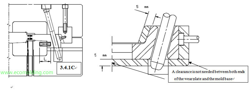
- The wear plate of the mold slider employs the 2510 steel, of which the hardness reaches up to HRC50°-52°. For all sliders with a thickness of over 50.0mm, wear blocks should be placed on the base and the back. These wear plates measure 5mm in thickness, and are 0.50mm higher than the mold base. And for all the sliders, a clearance is not needed along the travel direction of the slider (as shown in the following Fig.)
- The width and height of the slider clamp – made from the 2510 steel with a hardness of up to HRC50-52 – are 20mm and 20mm respectively, while the length is dependent on slider.
- Mold Slider Return and Fastening Method
For upward (including inclined ones) sliders, there are raised fine inserts and pins. When there’s an ejector pin under the slider, a spring can be applied to facilitate return.

- Requirements for Spring Location Design
- Spring is built in the mold core and the slider (see 3.4.1A, 3.4.1B and 3.4.1C)
- If the travel distance of the slider is long with an installation length of over 50mm, the spring may be mounted outside.

- Air/Hydraulic Cylinder driving
If the height of the guide pin is larger than 100mm (see Fig. 3.7.1A) and the cavity slider needs to be lifted before A and B plates separate from each other, a Air/Hydraulic cylinder may be applied to drive it (see Fig. 3.7.2B).


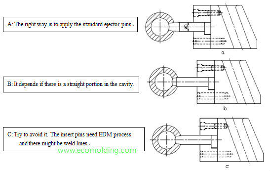
- Design Standard of Slider Inserts (Pins)
- Design Standard of Slider Stops
For the undercut of a circular product with sliders on 4 sides, a stop needs to be mounted to the slider insert. It is better to design a separate stop for each individual product if there are multiple products in a single mold.
