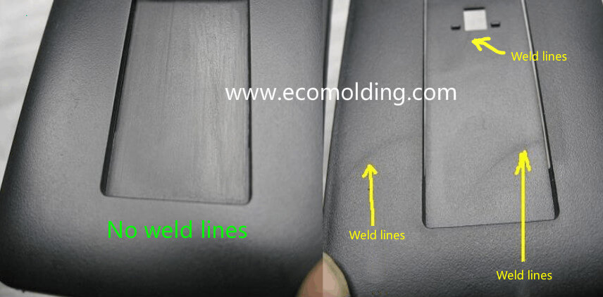
The definition of weld lines: When multiple plastic flow fronts meet in the cavity after encountering inserts, holes, or areas with inconsistent flow rates or interrupted melt flows, or in the case of gate injection filling, the inability of two or more flow fronts to fully “knit” together will cause the linear weld marks. The appearance of weld lines greatly reduces the mechanical strength of the product. The solution to the weld lines is basically the same as the method for reducing product sink marks.
I. Equipment
To respond to poor plasticization and uneven melt temperature, the molding cycle can be extended to make plasticization more complete, and select the molding machine with a higher plasticizing capacity when necessary.
II. Mold
(1) When the mold temperature is too low, raise the mold temperature appropriately or purposefully raise the local temperature at the weld seam.
(2) When the runner is too small, narrow or shallow, and the cold slug well is too small – Increase the dimensions and efficiency of the runner, as well as the volume of the cold slug well.
(3) Increase or reduce the gate section and change the gate location. The gate should be designed to prevent the melt from flowing around the inserts and holes. For the gate where injection filling occurs, we should try to correct, relocate or add a block buffer to it. Try to avoid the application of multiple gates.
(4) Poor venting or no vents. Open, expand or smoothen venting passages, including venting via insert and ejector pin clearances.
III. Molding Process
(1) Increase injection pressure and extend injection time.
(2) Properly adjust the injection speed: a high speed allows the melt reach the meeting point before it is cooled down, while a slow speed allows enough time for the air in the cavity to be vented.
(3) Properly adjust the temperature of the barrel and the nozzle: the higher the temperature, the smaller the viscosity of the plastic, the smoother the flow, and the thinner the weld line is; When the temperature is low, the decomposition of gaseous substances is reduced.
(4) The release agent should be used as little as possible, especially the silicone release agents, otherwise the flow fronts will fail to weld.
(5) Lower the clamping force to facilitate venting.
(6) Increase the screw speed to reduce the viscosity of the plastic; increase the backpressure to improve the density of the plastic.
IV. Raw Material
(1) Dry the raw material and minimize liquid additives in the formulation.
(2) Appropriately add lubricants and stabilizers to the plastic that features a poor fluidity or high heat sensitivity. When necessary, select a plastic that has a better fluidity or higher heat resistance.
V. Product Design
(1) When the wall thickness is small, the part should be thickened to avoid premature solidification.
(2) Make adjustments when the insert is not properly located.