What Causes Jetting in Plastic Injection Molding Product?

jetting plastic injection molding defects

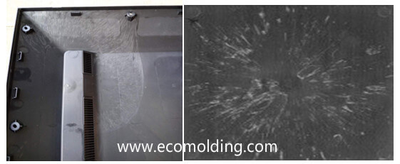
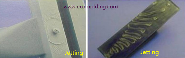
Jetting, also known as jet, worm track, or snake-like pattern, refers to the snake-like curves on a plastic injection molded part along the flow direction from the gate, as shown in Figure 1. Under normal circumstances, the molten plastic fills the mold cavity in a “fountain flow” manner, as shown in Figure 2, which depicts the “fountain flow” in detail. However, when the molten plastic flows at a high speed through narrow areas, such as the nozzle, the runner and the gate, and then suddenly enters an open and relatively wider area, the plastic melt will be injected from one end to the other of the cavity in the form of jet streams, creating folded strips. The melt that enters the cavity later fills the remaining space in the mold cavity with a normal fountain flow and is welded to the jetted streams. Since the melt is immediately cooled the moment it makes contact with the cavity wall (mold surface) which has a relatively low temperature, making the temperature of the jetted material lower than that of the fountain stream that comes later, thus causing poor welding and obvious jetting on the surface of the product. Study shows that the root cause of jetting is related to the mold design on the one hand and the viscoelasticity of the material on the other. From the perspective of the mold, when the molten plastic reaches the gate through a larger-sized runner, the flow resistance of the melt is greatly increased because the gate size is usually very small. In order to pass through the gate, the pressure output of the injection molding machine sharply increases. Accordingly, the pressure of the melt increases greatly, and a sizable shrinkage occurs, so when it subsequently enters an open and large-sized mold cavity, the resistance suddenly decreases, the pressure is suddenly released and the volume expanded to generate the jetting. The larger the melt pressure difference before and after entering the gate, the easier it is to form jet streams. The smaller the gate, the greater the pressure, the faster the speed, the greater the energy for the melt to fly out, and the more severe the jetting is. From the perspective of materials, the plastic melt features viscoelasticity. When the polymer melt is extruded through a die, the cross-sectional area of the extrudate is larger than that of the die exit, i.e., die expansion. For the filler material, the addition of fillers such as talc, calcium carbonate, and various glass fibers will greatly reduce the viscoelasticity of the material, so the possibility of jetting of the filler material is greatly increased. In addition, the more the filler material, the more likely it is to cause jetting.

Jetting Solutions in terms of mold design

1) Increase the gate size

2) Change the gate location

3) Change the gate type

Solutions in terms of molding process

1) Adjust the injection speed

2) Adjust the melt temperature

3) Raise the mold temperature

4) Increase the holding pressure

Solutions in terms of material

1) Improve the viscoelasticity of the material. Generally speaking, the greater the viscosity of the material, the lower the fluidity, the stronger the viscoelasticity, and the less likely it is to cause jetting. However, as mentioned above, for the filler materials, increasing the fillers may reduce the viscoelasticity, as well as the fluidity of the melt, thereby making it easier to cause jetting.

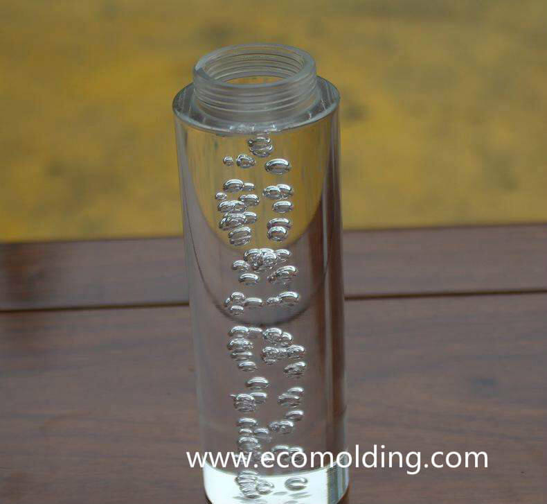
2) Reduce the amount of gas in the material. During the blending modification of plastics, the addition of various additives, the shear mixing of the screw, and the handling of small molecules by the equipment all affect the gas content inside. When the gas content is high, it causes a layer of small molecules to be attached to the front edge of the melt, which makes it more difficult to vent the gas generated during jetting. In the worse-case scenario, the front edge of the melt is burnt or cavitated.

What causes silver streaks or marks during injection molding?

silver streaks,silver marks

Definition of silver Streaks:

Silver streaks are also referred to as silver marks, which appear like burst blisters on the surface of injection molded parts, mostly in the shape arrows pointing to the gate.

Causes of Silver Streaks:

I. Equipment

1. The nozzle hole is too small, the material leaks or draws at the nozzle, or the barrel or the nozzle is obstructed, and the material decomposes due to the frictional heat caused by high-speed melt flow;

2. The barrel and the screw wear, or melt flow dead ends exist in the screw cap and collar, which are decomposed due to long-time heating.

3. The heating system is out of control, causing the temperature to be too high and resulting in decomposition. Check whether there are any problems with the heating elements such as thermocouples and heating coils. Improper screw design also leads to decomposition or brings in air.

II. Mold

1. Due to design defects, such as poor gate location, too small gate, asymmetrical gate deployment, small runner, and improper mold cooling system, the mold temperature varies a lot, so the melt doesn’t flow smoothly in the cavity, which blocks the passage of air.

2. The corners are too sharp, and the shear force is too large when the melt passes by, thereby causing the occurrence of silver streaks; 

3. The mold parting surface is designed with no or insufficient vents, or the vents are blocked or inappropriately placed, with no clearances or gaps for venting, such as inserts and pins, so that the air in the cavity cannot be vented when the melt flows in. 

4. A rough mold surface creates a higher frictional resistance, causing local parts to be overheated, which decomposes the passing plastic.

5. The mold leaks oil, water, and air into the mold cavity, which easily causes silver streaks on the part surface.

III. Molding Process 

1. The material temperature is too high, which causes decomposition. If the barrel temperature is too high or the heating is imbalanced, the barrel temperature should be lowered step by step. If the temperature of the feeding section is too high, part of the plastic will melt prematurely and fill the groove, making it impossible to vent the air through the feeding port.

2. When the injection speed is too fast, the molten plastic will be decomposed by the large shear force, and gas is accordingly generated; if the injection speed is too slow, the product cannot be filled in time, causing an insufficient surface density, and thus the silver streaks.   

3. Insufficient material, too large feeding buffer, too low material temperature or too low mold temperature will affect the fluidity and molding pressure of the melt, and thus generate voids.

4. During pre-molding, if the screw backpressure is too low and the speed is too high, the screw will return too fast, so that the air is easily pushed to the front end of the barrel together with the material.

IV. Material

1. A large amount of dust is mixed into the raw materials or mixed with the pellets, which is easy to entrain air during the melting process, and sometimes silver streaks are caused. When the raw materials are contaminated or there is too much dust, the raw materials are easily decomposed when being heated.

2. Too much sprue (recycled material) is added, the sprue is recycled for too many times, or a too high proportion of sprue is mixed with the new material (usually no higher than 20%).

3. The additives in the material decompose to generate silver streaks.

4. Excessively moist materials are not fully dried, resulting in silver streaks.

5. The material contains a high water content or is porous, which causes the silver streaks on the molded part.

What causes air bubbles or voids in injection molding?

air bubbles injection molding defects

According to the cause of air bubbles or vacuum voids , the solutions to the defects are described as below:

(1) When the wall thickness of the product is large, the outer surface is cooled down faster than the center portion. Therefore, as the cooling progresses, the resin at the center portion is expanded toward the surface while shrinking, so that the center portion is insufficiently filled. This situation is referred to as air bubbles, to which the main solutions are:

a) Determine the proper gate and runner size based on wall thickness. Generally, the height of the gate should be 50%-60% of the product wall thickness.

b) A certain amount of supplementary injection material is retained until the gate is sealed.

c) The injection time should be slightly longer than the gate sealing time.

d) Lower the injection speed and increase the injection pressure

e) Select a material with a higher melt viscosity.

(2) The air bubbles caused by volatile gases are mainly solved by:

a) Sufficient pre-drying.

b) Lowering the resin temperature to avoid gases caused by decomposition.

(3) Air bubbles caused by poor fluidity can be solved by raising the resin / mold temperature and increasing the injection speed.

Pantone Matching System Color Chart

The Pantone Color Matching System is largely a standardized color reproduction system. By standardizing the colors, different manufacturers in different locations can all refer to the Pantone system to make sure colors match without direct contact with one another.used in a variety of industries notably graphic design, fashion design, product design, printing and manufacturing and supporting the management of color from design to production, in physical and digital formats, among coated and uncoated materials, cotton, polyester, nylon and plastics.

Please click below link for Pantone color chart

PANTONE-color chart

Pantone color chart

RAL Color Chart

RAL COLOR CHART

RAL is an European color matching system which defines colors for paint, coatings and plastics. The RAL color standard is administrated by the RAL Deutsches Institut für Gütesicherung und Kennzeichnung. ‘RAL’ is the abbreviation of ‘Reichs-Ausschuß für Lieferbedingungen und Gütesicherung’.

Please click the link as below for RAL Color reference

RAL Color Chart

RAL COLOR K7

Injection pressure,holding pressure and back pressure

1.Injection Pressure

Injection pressure is exerted by the hydraulic mechanism of the plastic injection molding system. This pressure is transferred from the hydraulic cylinder to the molten plastic through the molding screw, under which the molten plastic will be pushed to flow into the mold sprue (also known as the primary runner of some molds), the primary runner and the sub-runner via the nozzle of the plastic injection molding machine, and then finally get into the mold cavity through the gate. This process is referred to as the injection molding process or the filling process. The purpose of the pressure is to overcome the resistance occurring when the molten plastic is flowing; or to put it another way, the resistance occurring in the flowing process needs to offset by the pressure exerted by the injection molding machine, so as to facilitate smooth filling.

the screws for injection pressure of injection machines

During the injection molding process, the injection nozzle features the highest pressure in a bid to overcome the resistance to flow throughout the whole process. After that, the pressure shows a trend of gradual decrease from the nozzle to the melt front as the molten plastic flows further. If the mold cavity vents well, the final pressure on the melt front will be equivalent to atmospheric pressure.

The injection pressure on molten plastic is influenced by a diversity of factors. To sum up, there are 3 categories: (1). Material factors, such a material type, viscosity, etc.; (2). Structural factors, such as type, quantity and location of the runner system, shapes of mold cavity and product thickness, etc.; (3). Molding process factors.

2.Value & Time of Holding Pressure

When the plastic injection molding process is drawing to an end, the screw will stop rotating but only keep moving forward. At this point, the injection molding process enters the pressure holding phase, during which period of time the injection nozzle continuously feed materials into the cavity, to fill up the empty space caused by product shrinkage. If the pressure is not held after the cavity is filled up, the product will shrink for about 25%. In particular, shrink marks will be left near the ribs due to enormous shrinkage. Usually, the value of the holding pressure is about 85% of the top injection pressure, which, of course, is subject to actualities.

3.Back pressure

Back pressure refers to the pressure that the screw has to overcome during its return action after injecting material. The application of a high backpressure helps distribute the pigments and melt the plastic, but at the same time, it also extends the screw’s return time, decreases the length of plastic fibers and raises pressure in the injection machine. As a result, the backpressure should be kept lower, usually not exceeding 20% of the injection pressure. Some injection machines allow backpressure programming to compensate for screw travel decrease, which will reduce heat input, causing the temperature to drop. However, since it is not easy to predict the changeable result, corresponding machine adjustment will a troublesome task.