Material Change and Color Change tips during injection molding production

Changing material or color in the injection molding process certainly deserves in-depth discussion. A quick color or material change cannot only save time, but also drastically bring down the production cost.

change material or change color during injection molding

1)Color change – a same material

In principle, when injection molding factory change the color of a same material, change from light to dark is usually easier than that from opaque to transparent.

The regular color change procedure is described as below:

  • Shut the feed inlet located in the lower part of the feed hopper;
  • Perform several empty shots, until the previous material is cleared from the barrel;
  • Feed the new material into the hopper;
  • Open the feed inlet, and pull the screw back and forth for a dozen times until changeover is completed.

When changing from an opaque material to a transparent material, the nozzle needs to be removed to clear the residue; if necessary, the screw needs to be pulled out for thorough cleaning to make sure that there is no residue hiding in the corners.

2)Color change – a different material

Concerning switch between different materials, the material change steps are performed on basis of the viscosity difference between the materials, as well as barrel temperature control.

Thermoplastics tend to adhere to metal surface at a high temperature; and the situation is the opposite when the temperature is low.

The change of materials can take advantage of this feature – make the previous material in the barrel adhere to barrel surface, and then help the high-viscosity remover material clean it with the involvement of cold screw. At this point, the screw temperature needs to be low enough, so that the previous material will not adhere to it, thus easy for purge. Therefore, the remover material needs to possess a high melt viscosity, such as high-density PE or PS.

Keep the following considerations in mind when switching materials:injection mold factory in china

  • Before changeover is done, the barrel temperature needs to be lower than the actual molding temperature; for example, when changing from the low molding temperature material A to the high molding temperature material B, the purging temperature of material B should be 10℃ – 20℃ lower than its molding temperature; and when changing from the high molding temperature material B to the low molding temperature material A, the purging temperature of material A should be 10℃ – 20℃ lower than its molding temperature.
  • Reduce screw rotation speed and screw backpressure, to prevent material temperature rise caused by frictional heat;
  • Try to prevent the material (molten) to be replaced from adhering to the screw;
  • Apply short screw travel to flush the material for several times, to achieve the best effect for material change;
  • If there are scars or gaps on the barrel inner surface, or the screw head, outer surface or groove, the molten material may be stuck at such locations, thus making it hard for material change.

3)Practical operation of material change

During the plastic injection molding process, changing material or color happens a lot. If sufficient basic knowledge of material change is not equipped, waste of time and money may probably be caused to the manufacturer. To respond to the challenges posed by changeover, the Germany-made CORATEX purging agent has been introduced to clear the residues left in the screw, the nozzle and the mold (especially ideal for cleaning of hot runner molds), which is very helpful for reducing the time consumed by changeover.

Material switch operation for PC

From PC to ABS

(1) Shoot all remaining PC out from the barrel;

(2) Within the molding temperature range of PC, use high-density PE to clear the residual PC from the barrel;

(3)   Bring barrel temperature down below 220℃, and use ABS to clear the high-density PE, then changeover is completed.

From PC to POM

(1)   Shoot all remaining PC out from the barrel;

(2)   Within the molding temperature range of PC, use high-density PE to clear the residual PC from the barrel;

(3)   Bring barrel temperature down below 190℃ and use POM to clear the high-density PE, then changeover is completed.

From PC to PMMA

(1)   Shoot all remaining PC out from the barrel;

(2)   Within the molding temperature range of PC, use high-density PE to clear the residual PC from the barrel;

(3)   Bring barrel temperature down to 240℃, use non-dried (moist is not removed) PMMA to clear the high-density PE and then clear it with dried PUMA. The changeover is then completed.

From PC to PP

(1)   Shoot all remaining PC out from the barrel;

(2)   Within the molding temperature range of PC, use PP to clear the residual PC;

(3)   Bring barrel temperature down to 200℃, and use HIPS to clear the high-density PE, then changeover is completed.

Material change operation for ABS

From ABS to PC

(1)Shoot all remaining ABS out from the barrel;

(2)   Within the molding temperature range of ABS, use high-density PE to clear the residual ABS from the barrel;

(3)   Raise barrel temperature to 290℃, and use PC to clear the PE, then changeover is completed.

From ABS to POM

(1)   Shoot all remaining ABS out from the barrel;

(2)   Within the molding temperature range of ABS, use PS to clear the residual ABS from the barrel;

(3)   Bring barrel temperature down to 190℃ and use POM to clear the PS, then changeover is completed.

From ABS to PMMA

(1)   Shoot all remaining ABS out from the barrel;

(2)   Within the molding temperature range of ABS, use PS to clear the residual ABS from the barrel;

(3)   Keep barrel temperature at 240℃, use non-dried (moist is not removed) PMMA to clear the PS and then clear it with dried PMMA. The changeover is then completed.

Material switch operation for POM

From POM to PC

(1) Shoot all remaining POM out from the barrel;

(2)   Within the molding temperature range of POM, use PE to clear the residual POM from the barrel;

(3)   Raise barrel temperature to 290℃ and use PC to clear the POM, then changeover is completed.

Material switch operation for PP

From PP to PC

(1)   Shoot all remaining PP out from the barrel;

(2)   Raise barrel temperature to 290℃ and use PC to clear the PP, then changeover is completed.

From PP to POM

(1)   Shoot all remaining PP out from the barrel;

(2)   Keep barrel temperature at 190℃ and use POM to clear the PP, then changeover is completed.

From PP to ABS

(1)    Shoot all remaining PP out from the barrel;

(2)    Keep barrel temperature at 240℃ and use ABS to clear the PP, then changeover is completed.

From PP to PMMA

(1)    Shoot all remaining PP out from the barrel;

(2)    Keep barrel temperature at 240℃, use non-dried PMMA to clear the residual PP from the barrel and then clear it with dried PMMA. The changeover is then completed.

From PP to HIPS

(1)    Shoot all remaining PP out from the barrel;

(2)    Keep barrel temperature at 240℃ and use HIPS to clear the PP, then changeover is completed.

Injection Molding Defects’Causes & Countermeasures

The causes and countermeasures described below are aimed to solve the commonly seen  injection molding defects that might occur in ordinary circumstances. The examples are just based on my own personal work experience, so if there is anything inappropriate, you are welcome to correct me!

Short shots (incomplete filling)

(1) Short shots (incomplete filling): The molten plastic fails to fill up each and every corner in the entire molding space (the cavity).

(2) Causes and Countermeasures

short shot injection molding defects


Flash
 

(1) Flash: Extra plastic material in the shape of films or burrs, which appears on the parting surface, around the runner or in the insert crevice.

(2) Causes & Countermeasures (See the table below)

flash,burrs injection molding defects
*Note: Flash also tends to occur when the injection pressure/speed are too high, but molding time is too long and mold temperature is too low.

Silver streaks

(1) Silver streaks (silver lines): The radial silver white streaks on or around the product surface, which is formed along the plastic flow direction.

(2) Causes & Countermeasures (See the table below)

silver strike injection molding defects


Low product glossiness
 

(1) Low product glossiness means the surface glossiness of the product does not meet the quality standard – the surface is not dioptric.

(2) Causes & Countermeasures (See the table below

Low product glossiness injection molding defects

Deformation

(1)Deformation includes diagonal twists and warpage along parallel edges.They are the irregular curves that occur in the plastic injection molding process.

(2)Causes & Countermeasures (See the table below)

Deformation injection molding defects


Ejecting marks
 

(1) Ejecting marks (AKA white marks): The white marks that occur in the ejector pin or other ejecting positions during mold release.

(2) Causes & Countermeasures (See the table below)

ejecting marks injection molding defects

Weld lines

(1) Weld lines: The thin lines that occur when 2 or more molten materials are fusing in the plastic injection molding process.

(2) Causes & Countermeasures (See the table below)

welding lines injection molding defects


Jetting marks

(1) Jetting marks: The streaks that the molten plastic produces around the gate.

(2) Causes and Countermeasures

jetting marks injection molding defects  

Discoloration (black marks)

(1) Discoloration (black marks): The black marks or other dark marks that appear on the product surface during the plastic injection molding process.

(2) Causes & Countermeasures (See the table below)

Discoloration (black marks) injection molding defects

Bubbles

(1) Bubbles: The residual voids sealed up in the product, which are caused by the evaporation of the moist contained in the molten plastic.

(2) Causes & Countermeasures (See the table below)

Bubbles injection molding defects

Why is Mold Temperature So Important for Plastic Injection Molding?

In the plastic injection molding industry, some newcomers often ask: why the final plastic parts have a higher gloss when the mold temperature is higher. Now in plain language, let’s explain this phenomenon, as well as how to appropriately select the right mold temperatures.

mold temperature control

1,Influence on Product Appearance:

First of all, a too low temperature will affect the fluidity of the molten plastic, leading to incomplete filling; mold temperature influences the crystallinity of plastic materials. For ABS materials, if the temperature is too low, the final product will have a lower gloss. Compared with the filler, plastic tends to move to the surface when put under the high temperature condition. Therefore, a higher temperature will allow the plastic to contact with mold surface more closely, thus ensuring better filling, as well as higher brightness and gloss. Yet, the temperature of the plastic injection mold cannot be too high, or sticking to cavity will be caused and bright spots will also appear in some local areas of the plastic part. On the other hand, if the mold temperature is too low, the plastic part will be clamped so tight that it may be damaged during mold release, in particular the surface texture of the plastic part.

Multi-stage injection is able to solve positional problems. For example, we can employ the multi-stage injection approach to solve product gas marks caused during the filling process. In the plastic injection molding industry, the gloss level of a smooth surfaced product will be higher when the mold temperature is high, and verse versa. However, for textured PP products, the higher the temperature, the lower the gloss, and the larger the color difference – the gloss is inversely proportional to the color difference.

As a result, one of the most common problems caused by mold temperature is the rough surface of the plastic injection molded part, which is mainly because the surface temperature of the mold is too low.


2,Influence on Product Dimensions:

If mold temperature is too high, the molten plastic will probably decompose and the shrinkage rate of the plastic product will be larger when exposed to air, leading to shrunk product dimensions. When a mold is used under a low-temperature condition, if product dimensions are increased, the most likely cause is the very low surface temperature of the mold. The reason is that when the mold surface temperature is too low, the molded product will have a lower shrinkage rate when exposed in the air, so the dimensions are larger – the reason being that the low mold temperature will accelerate the molecules “freezing tendency”, creating a thicker frozen layer of the molten plastic inside the mold cavity. At the same time, the low temperature will also impede the crystallization process, therefore the shrinkage rate of the molded product is decreased. On the contrary, higher mold temperature will slow down the cooling process of molten plastic, resulting in a longer relaxation time and a lower level of tendency, while also facilitating crystallization. Thus, the actual shrinkage rate of the product will be higher.

If the startup process is very long before the dimensions stabilize, it means the temperature is not appropriately controlled, because it takes a long time for the mold to reach thermal balance.

Uneven heat radiation at some parts of the mold will greatly extend the production cycle, causing the injection molding cost to rise. A consistent mold temperature is able to minimize the fluctuation of molding shrinkage rate, thus enhancing dimensional stability. For crystalline plastics, a high temperature is helpful for the crystallization process, while a fully crystallized plastic part is subject to minimal dimensional changes during storage or application. However, the higher the crystallinity, the higher the shrinkage rate. For soft plastic materials, a low mold temperature is recommended in the molding process, which is helpful for dimensional stability. For all the materials, it is true that consistent mold temperatures and shrinkage rate are helpful for improvement of dimensional accuracy.


3. Influence on Product Deformation:

If the mold cooling system is not reasonably designed or the mold temperature is not appropriately controlled, part warpage will be caused due to insufficient cooling. To ensure proper mold temperature control, the temperature difference between the cavity side and the core side should be defined on basis of the structural characteristics of the plastic product. We can offset the shrinkage differences caused by molecular orientation and therefore avoid orientational part warpage by controlling the different cooling and shrinkage speeds at different parts of the mold while also considering the characteristic that the part tends to warp towards the side where the temperature is higher after mold release.

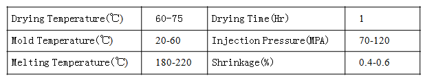
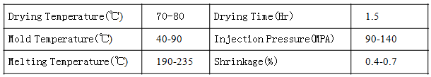
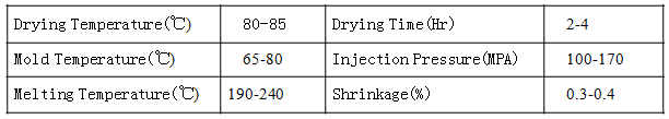
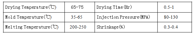
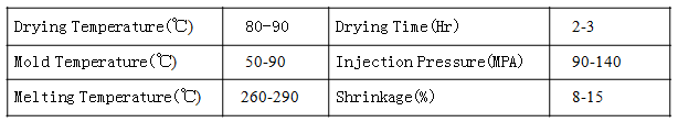
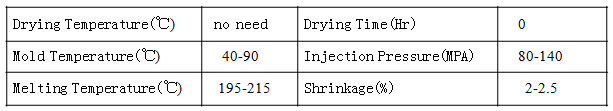
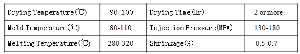
For fully symmetrical parts, the mold temperature should be kept consistent to guarantee cooling balance within the entire part. A consistent mold temperature and balanced cooling is able to minimize part deformation. On the contrary, if the mold temperature difference is too large, uneven part cooling will be caused, leading to inconsistent shrinkage, and the internal stress thus caused will make the plastic part warp. This is especially true for plastic parts with an uneven wall thickness and a complicated shape. The product will definitely warp towards the mold side where the temperature is higher. It is suggested that the temperatures of the cavity side and the core side should be properly selected depending on actual needs. Please refer to the Material Property Table for mold temperatures.


4,Influence on Product Mechanical Properties (Internal Stress):

A low mold temperature will lead to obvious welding lines on the plastic part, which reduces the product strength; with regard to crystalline plastics, the higher the crystallinity, the more likely stress cracks will appear on the plastic product. To reduce internal stress, the mold temperature should be kept at a moderate level (PP, PE). As for the amorphous plastic materials like PC which possess a high stickiness, the stress cracks are associated with the internal stress of the plastic part. So, it will help reduce internal stress by raising mold temperature, so as to reduce the tendency towards stress cracks. The internal stress is usually indicated by obvious stress marks.

The reason is: basically, the internal stress occurring in a molding process is caused by the different thermal shrinkage rates during cooling. After the plastic product is molded, cooling will take place and extend from the surface to the core. The surface shrinks and solidifies first, and then gradually extending to the inside. During this process, the internal stress is caused due to the difference in shrinkage speed. When the residual stress inside the part is higher than the elasticity of the resin material or the part is corroded in a chemical environment, cracks will appear on the part surface.

The research into the PC and PMMA transparent resin materials indicates that, the residual stress shows a contracted form on the surface layer but a stretched form on the inside. The compressive surface stress is dependent on the surface cooling conditions. A cold mold is able to cool down the molten resin in a very fast way, so that a high level of residual stress is produced in the molded product. Mold temperature is one of the fundamental conditions for internal stress control. A slight change in mold temperature may make a great difference to residual stress. Generally speaking, the acceptable internal stress of each product and resin material has its lowest limit. When molding a thin-walled product or the flow distance is long, the lowest mold temperature should be higher than that applied to common molding.


5,Suggestions on How to Identify the Right Mold Temperatures:

Nowadays, molds are becoming more and more complex. As a result, it is getting harder for us to create appropriate conditions for mold temperatures control. In addition to simplifying the part, the mold temperatures control system is usually a compromise solution. Therefore, the following suggestions only serve as a rough guide.


During the mold design phase, temperature control of the molded part must be taken into consideration. For example, when designing a low-volume large-size plastic injection mold, one of the most important considerations is the cooling performance. Concerning the molds for production of precision parts, or of the parts that have to meet stringent appearance or certain safety standards, a higher temperature is usually applied (ensuring lower shrinkage rate, glossier surface and consistent performance). For parts that require lower technologies and minimal production costs, a lower temperature should be applied during the molding process. Nevertheless, manufacturers should be aware of the respective weaknesses of the choices and perform careful inspection of the parts, to make sure that the produced parts are still able to satisfy customer requirements.

Common Plastics Material Character and Performance

Plastic Resin Injection Molding Process Characteristics

Polystyrene (PS)


1. PS Performance: (Hard Plastic)

PS is an amorphous polymer with a density of around 1.04g/cm3, AKA standard plastic.

With favorable fluidity and a low water absorption rate (lower than 0.02%), it is a transparent plastic material that is easy to plastic injection molding process. PS product’s light transmissionrate are typically as high as 88 – 92%, with strong tinting strength and high hardness; It is also non-toxic and odorless.

However, PS products are highly brittle, stress cracks tend to appear (may be checked by soaking or wiping with kerosene); poor thermal resistance (60~80℃).


2. PS Applications:

Ornaments, illuminated signs, lampshades, stationery, transparent toys, daily necessities, kitchen supplies, cups, meal boxes, cassettes and mirrors, etc.


3. PS Process Characteristics:

The melting point and decomposition temperature of PS are 166℃ and 280℃ respectively. Thanks to its good fluidity and the low flow resistance, the injection pressure can be a little lower.

As the PS features a lowspecific heat, the produced parts can soon solidify after mold cooling. Its cooling speed is higher than other materials, so mold open time can be earlier. Both its plasticizing time and cooling time are a relatively shorter, leading to a shorter molding cycle.

Internally stressed plastic parts can be soaked in 65 – 80℃ water for 1 – 2 hours, then gradually cooled to the room temperature, and the internal stress can be removed.

The barrel does not need to be cleaned after the machine stops, because the PS itself can be used as the cleaning agent of other plastic materials.


PS Plastic Injection Molding Process Characteristics


Acrylonitrile Butadiene Styrene (ABS)

1. ABS Performance: (Acrylonitrile Butadiene Styrene )

ABS is an amorphous polymer with a density of around 1.05g/cm3. Its overall performance is great, with high mechanical strength, excellent impact resistance, certain surface hardness and anti-abrasion properties. Its heat resistance is as high as 90℃ (even able to be used under the 110 – 115℃ temperature conditions); good low temperature resistance (able to be used under the -40℃ temperature conditions); and allowing easy processing and easy electroplating.

But it has poor solvent resistance; easy to age when exposed to UV rays; low extension rate. ABS features a diversity of varieties and an extensive range of applications, so it is also known as “general purpose engineering plastic”.


2. ABS Applications: :

Electronic product parts, toys, casings and daily necessities, etc.


3. ABS Process Characteristics:

(1) ABS has poor moisture absorption and temperature resistant properties. Before the molding process, it must be dried and preheated thoroughly, to keep its moisture content below 0.03%.

(2) The proper injection molding processing temperature of ABS is normally kept between 210 and 250℃.

(3) The best effect will be achieved when ABS is used for injection production at a medium injection speed (unless the structural complexity and thickness of the product require a higher injection speed. Gas marks tend to appear around the gate of the product.

(4) ABS should not stay for too long inside the high-temperature barrel (should be kept less than 30m), or it will easily decompose and turn yellow. When changing from another material to ABS, the plastic injection machine needs to be cleaned with PP or PE.


 ABS Plastic Injection Molding Process Characteristics


Acrylic (PMMA)


1. PMMA Performance:

PMMA is an amorphous polymer (commonly known as Acrylic), with a density of around 1.18g/cm3. It is extremely transparent, with a light transmission rate of as high as 92%; featuring good thermal resistance (heat deflection temperature is 98℃) and high hardness. But, if it is used as an optical product material, the surface will be easily left with scratches. Its biggest weakness is brittleness (better than that of PS).


2. PMMA Applications:

Lampshades, window glasses, signs, optical lenses, contact lenses and automotive parts, etc.


3. PMMA Process Characteristics:

PMMA has stringent processing requirements. As it is very sensitive to moisture and temperature, thorough drying is required before molding. The molten PMMA is highly sticky, so it needs to be processed under high temperature (190 – 240℃) and high pressure conditions. It is better if the mold temperature is kept between 65 and 90℃. PMMA does not feature a good thermal stability, so degradation may occur when it is put under high temperature or stays in a high temperature environment for too long. “Hollows” tend to appear inside thick PMMA products, so it is better to be processed using a big gate and under the “high material temperature, high mold temperature and slow speed” injection conditions.


 PMMA Plastic Injection Molding Process Characteristics


Polypropylene  (PP)


1. PP Performance:

PP is a crystalline polymer, with a density of as low as 0.91g/cm3. Among the commonly used plastics, PP is the lightest; and among all general-purpose plastics, PP is the most thermal resistant – its heat deflection temperature is 80 – 100℃ and can be heated in boiling water.

PP features a strong stress crack resistant property and bending fatigue resistance, and it is also commonly known as “polypropene”.

PP is lightweight, with good toughness and chemical resistance.

PP weaknesses: low dimensional accuracy, insufficient rigidity, poor weatherability. It ages and thus becomes brittle easily. During the application process, long time contact with copper should be avoided, so as to prevent the “damage by copper”.


2. PP Applications:

Various household items, transparent pot covers, chemicals delivery pipelines, chemicals containers, medical supplies, stationery, toys, wires, cups、circulating boxes, pipes and hinges, etc


3. PP Process Characteristics:

PP possesses good fluidity under the melting temperature, with great molding capabilities.

High molecular orientation, leading to high shrinkage rate.

It is better that PP processing temperature is kept between 200 and 250℃, as it shows excellent thermal stability (decomposing temperature is 310℃).

To improve shrinking deformation and dents, the mold temperature should be kept between 35 and 65℃. The crystallization temperature of PP is 120 – 125℃.

The molten PP is able to flow through the narrow gaps in a mold, thus causing flash. During its melting process, PP will absorb a large amount of heat of solution (high specific heat), so the product is very hot after the mold opens.

The PP material does not need to be dried when processing. The shrinkage rate and crystallinity of PP is lower than that of PE.


 PP Plastic Injection Molding Process Characteristics


Polyamide (PA)


1. PA Performance:

Commonly known as nylon, PA is also a crystalline polymer, with a density of 1.13g/cm3. Among its diversified varieties, the nylon materials that are used for injection molding typically include Nylon 6, Nylon 1010 and Nylon 610 etc.

Nylon’s advantages include high mechanical strength, high toughness, as well as fatigue resistance, smooth surface, self lubrication, low abrasion coefficient, resistance to abrasion/heat (allow long-term use below 100℃), corrosion resistance and easy processing, etc.

PA weaknesses: easy water absorption, imposing stringent requirements for injection molding, poor dimensional stability, and very hot product upon mold ejection due to the high specific heat.

Among the PP materials, PA66 has the highest mechanical strength and enjoys the most extensive scope of application. Thanks to its high crystallinity, both its rigidity and thermal resistance are very high.


2. PA Applications:

High temperature electric socket parts, electric parts, gears, bearings, rollers, pulleys, spring supports, screws, impellers, fan blades, propellers, high pressure seal gaskets, valve carriers, oil pipelines, oil containers, cables, cable ties, driving belts, grinding wheel adhesives, battery boxes, electrical insulator parts, wire cores and wires, etc.


3. PA Process Characteristics:

Due to its high moisture absorption rate, PA must be dried before processing, to bring its moisture content below 0.25%. The drier the raw materials, the better, then the surface gloss of the product can be guaranteed, or it will be very rough.

PA will not soften with the rise of temperature. With the obvious melting point, it will flow the moment the temperature reaches the melting point (different from PS, PE and PP etc.); one of the rheological properties of the nylon material is that its stickiness is not sensitive to shear rate.

Due to its high fluidity, though PA fills the mold easily, flash or burrs tend to occur.

PA features both high melting point and freezing point. The molten PA can become solid at any time with the temperature falling below the freezing point, which hampers the filling and molding process, causing nozzle or sprue blockage. Therefore, high speed injection must be adopted (especially for thin-walled products or long running productions), so as to minimize pressure holding time. In addition, nylon molds need sufficient ventilating measures.

Molten PA has poor thermal stability and is prone to degradation. Normally, the barrel temperature should not exceed 300℃, and the molten material should not be heated in the barrel for more than 30m.

PA imposes high requirements for mold temperature. Its crystallinity can be controlled by mold temperature, so as to acquire the desired performance. It is better if the temperature of PA injection molding can be kept between 50 and 90℃.

Sometimes, a PA product needs “conditioning”, to improve its toughness and dimensional stability.


 PA nylon Plastic Injection Molding Process Characteristics


Polyoxymethylene (POM )


1. POM Performance:

POM is a crystalline polymer, with a density of 1.42g/cm3. It features high rigidity, and is also called “Acetal”.

It possesses many advantages, like fatigue resistance, abrasion resistance, thermal resistance and impact resistance, etc., with a low frictional coefficient and great self lubricating properties. Its heat deflection temperature is 172℃.

POM does not absorb moisture easily, so it maintains excellent dimensional stability in a moist environment, with a shrinkage rate of 2.1%, so it is not easy to control the dimensions during the injection molding process.

POM + 20%GF (glass fiber), shrinkage rate = 0.5%-1.5%.


2. POM Applications: :

Able to replace most of the nonferrous metals, vehicles, machine tools, instrumental internal components, bearings, fasteners, gears, leaf springs, pipes, delivery belt components, electric boilers, pump shells, grids and tap faucets, etc.


3. POM Process Characteristics:

Before processing, the POM material does not need to be dried, but it is better be preheated (at approx. 80℃) during the process, which will benefit product dimensional stability. The processing temperature range of POM is limited between 195 and 215℃. It will decompose if staying in the barrel for too long, or the temperature exceeds 220℃, generating strongly irritant formaldehyde gas. During the injection molding process of the POM material, a high packing pressure is needed (close to the injection pressure), to minimize pressure drop. The revolving speed of the screw cannot be too high, and the residue should be kept as little as possible; POM products feature a high shrinkage rate, and are prone to shrinkage or deformation. With the high specific heat and mold temperature (80 – 100℃), POM products are very hot upon mold injection, so it is necessary to prevent your fingers from being burnt. Ideally, POM needs to be molded under the “medium pressure, medium speed, low material temperature and high mold temperature” conditions. When producing precision products, a mold temperature controller is needed to control the temperature of the mold.


 POM Plastic Injection Molding Process Characteristics


Polycarbonate (PC)


1. PC Performance:

With a density of 1.2g/cm3 and excellent transparency, PC is commonly known as the bulletproof plastic. It possesses an outstanding overall performance that is characterized by “toughness and rigidity”, with high mechanical strength, great toughness, extremely high resistance to impact, outstanding thermal resistance & weatherability, accurate dimensions and high stability. Besides, it is also non-toxic and odorless.

The thermal deformation temperature of PC is between 135 and 143℃, allowing long-term application under the 120 – 130℃ temperature conditions.

PC weaknesses: Poor chemical resistance, low fluidity, sensitive to moisture, and prone to internal stress cracks, etc.


2. PC Applications:

High temperature electric products, air blower shells, transformer casings, electric tools, motor casings, tool boxes, milk bottles, beverage dispenser casings, camera parts, safety helmets, gears, food trays, medical devices, ducts, hair pins, hair dressing tools, shoe heels, structurally stronger engineering parts after being fiber reinforced, and CD discs, etc.


3. PC Process Characteristics:

The PC material is very sensitive to temperature – the stickiness of the molten PC apparently falls with the rise of temperature, leading to a faster flow speed; but it is not sensitive to pressure. To improve its fluidity, the faster way is to raise the temperature. Before processing starts, the PC material needs to be dried thoroughly (at 120℃), to keep moisture content below 0.02%; the appropriate molding conditions of PC is “high material temperature, high mold temperature, high pressure and medium speed”. The mold temperature is better be controlled between 80 and 110℃, while the ideal molding temperature is between 280 and 320℃. Gas marks tend to appear on PC product surface and the gate, and high internal stress will lead to cracks. Therefore, the PC material imposes high requirements for processing. With a low shrinkage rate (approx. 0.6%), its dimensional changes is minimal; the PC injection molded products can apply the “tempering” process to remove the internal stress.


PC plastic injection molding Process Characteristics

Special Mold Design for Complicate Structure

Eco molding is a very professional injection molding company since 1998, we have accumulated lots of experience in plastic injection mold design, Now we share some special mold design for the complicated product.


1) sliders in sliders

Special Mold Design(small slider in bigger one)

2) design for bend tube

Special Mold Design for bend fitness


3, the design of a circular cylinder

Special Mold Design for bend pipe


4, Tubes with logo


5, slider on Arc

Special Mold Design

6, slider run by gears

Special Mold Design for slider


7, special design

Special Mold Design


8, two times direction change

Special Mold Design for slider

Activity Levels Show Improvement of US Mold Makers

Most of the major economic indicators released at the end of 2007 signaled weaker business conditions for the U.S. manufacturing sector, but activity levels for North American mold builders bucked this trend and showed some improvement in recent weeks. Our Mold Business Index (MBI) for December is 53.7. This is a 7.2-percentage point increase from the November value of 46.5. Increases were registered in the core New Orders, Production, Employment, and Backlog components. The bad news came in the form of longer Supplier Delivery Times and higher Materials Prices. The Future Expectations held firm at 66.7 in December.

Orders for new molds increased ever-so-gradually during the second half of 2007. Growth during the first half of 2008 is expected to be sluggish,
but momentum is expected to build in the second half of the year.

The probability that the U.S. economy will soon fall into a recession has risen in recent weeks. However, we still believe the most likely scenario is that overall economic growth will decelerate, but remain positive through the first half of 2008. This means that total demand for new molds and tooling will remain very close to the current level in the first and second quarters of this year before growing more steadily in the second half of 2008. The downside risks to this forecast are the unpredictability of the crude oil market and the ongoing struggles in the residential construction sector. If energy prices remain at their current elevated levels, then the chances of a near-term recession in the U.S. economy increase significantly.
The American mold makers will benefit from the low value of the U.S. dollar versus the other major currencies throughout 2008, while the Canadian mold makers will remain pressured by the exchange rate situation. The current deceleration in the U.S. economy notwithstanding, global demand for plastics products is growing and capacity utilization rates for the plastics industry remain at a strong level.
The sub-index for New Orders of molds registered 58.3 in December, which means that overall new business was significantly higher when compared with the previous month. Future gains in the total MBI depend on continuing increases in new orders of molds. Production levels also escalated, as the latest Production sub-index was 63.9. The Employment component was 58.3, which means that there was a rise in overall payrolls last month. The Backlog component was higher at 52.8 in December.

Improving a Family Molding Program

Speed, flexibility and consistent part quality are the buzzwords for staying competitive in the cost-conscious American large automotive plastics molding marketplace.

When an MI-based corporation – a major automotive trim manufacturer – chose to upgrade its hot runner systems, it turned to Peabody, MA-based Synventive Molding Solutions as its partner because of the technological advantage that next generation smart molding systems could offer. Seeking to benefit from the ability to produce automotive trim parts at high speed with exceptional finish quality and part-to-part consistency, the company invested in Synventive Dynamic Feed hot runners to achieve a competitive technical and processing edge. Furthermore, the molder was able to successfully implement a family mold that produces separate and distinct parts, parts that exhibit exceptional dimensional stability and consistency – a target that the company struggled with until a smart molding system was used to process them.

Starting Up

In June of 2000, the entire plastics world invaded Chicago, IL – specifically the McCormick Place – to attend the National Plastics Exposition. At the show, Synventive unveiled the Dynamic Feed smart molding system, creating lots of interest in a hot runner system that brings incredible levels of control and accuracy to the injection molding process. Engineering managers at this automotive trim molder were very interested in the new technology. In fact, they were among the first customers to see a presentation on smart molding, and ultimately ordered five complete systems from Synventive in the summer of 2001.

The Dynamic Feed hot runner system is a proven technology that delivers unprecedented levels of control to the processor, offering molders the ability to individually control the fill and pack rates at each gate of a multicavity or family mold, or at each individual gate in a large multigated mold. The key to the control of this smart hot runner technology is that the control is in the hot runner nozzle, allowing molders to control the entire shot process with a closed-loop, real-time controller. Unlike machine optimization or mold balancing systems that seek to control elements other than the actual injection molding process, smart molding gives processors control of the very heart of the injection molding process.

After running a detailed internal return on investment analysis of the system, the company could see that a smart molding system offered the company a clear competitive advantage. The new technology was ordered on a tight timetable that gave Synventive just six weeks to deliver. In addition to the tight delivery schedule, Synventive needed to train the molder’s people in the optimal use and operation of smart molding technology.

Molding Challenges

According to the trim tooling manager at this automotive parts molder, the goal was to gain a speed and quality advantage in the marketplace with a hot runner system that had a quick setup time with excellent part-to-part consistency. The company turned to Synventive for those answers when it initiated this family molding program.

The Michigan firm planned to use the Dynamic Feed systems to help mold automotive instrument panel shrouds, a job that integrated several complicated elements into the mold. Its mold builder, Delta Tooling of Auburn Hills, MI, supplied the family mold for the project. The mold contained fine detailed elements plus a second molding operation to overmold a different color material onto the part. The family mold for the instrument panel shroud featured a small panel accent on the right side and a larger panel accent on the left side, with a cutout for an air conditioner vent. In addition, the shroud has a contrasting color accent molded onto it. The technical issue with the mold was how to manage the three-to-one ratio difference in shot weights for each of the accent panels, a situation where the machine must seal off the part in the mold to create a parting line with the overmolding process.

With the seal-off measuring just three eighths of an inch where normal injection molding standards are typically three inches or more, coupled with the complexity of dissimilar sized parts being molded simultaneously, it was clear that standard hot runner technology was not going to offer the speed and accuracy that the company desired. The molding process to manufacture the instrument shroud is very precise to ensure quality and cavity sizes, plus the seal-off tolerances meant that it was essential for the processor to have finite control of the injection fill and pack profiles of the cycle. This was even more essential due to the seal-off tolerances; any overshot and the entire part would be ruined. Similar to a waffle iron with too much batter in it that spills all over the countertop, the mold seal will blow if the mold is overshot, requiring a very precise injection molding process. The entire process took place in a family mold, also adding to the complexity of the molding process.

Synventive Molding Solutions recommended a Dynamic Feed system based on the need for precision and due to the dissimilar sized accent panels being molded. That ruled out using a more conventional sequential valve-gated system, because of the need to balance the mold parameters and the injection molding process so precisely.

Going Online

Before the program could begin, Synventive and Delta Tooling needed to test the molding process and machinery to assure their client that the hot runner system and the family mold would work as advertised. The two firms tested the systems and mold at Delta’s test center, where the two companies had a short learning curve implementing the new smart molding technology and family mold. The focus of the testing was on start-up procedures, which proved to be easily mastered. Moreover, the testing allowed for the complex family mold to be dialed in by the Synventive and Delta technicians, who could adjust the rate of fill and pack pressures needed to create dimensionally stable, top quality parts cycle after cycle. Most importantly, the test site allowed the Synventive team to bring together the injection molding machines, the family mold, the smart molding system and the plastic material suppliers under one roof to get a real world construct of how the program would ultimately come together. All parties at the site were very pleased with the consistency and repeatability of the smart molding process.

Meanwhile, the Synventive team was working overtime to make sure the Dynamic Feed systems would be delivered on time and to specification. The order was met by coordinated efforts in Peabody with the engineering and manufacturing staff. And, although the timing was tight and Synventive and Delta had to put in long hours to make it happen – including training the molder’s operators on using the system at the plant – Synventive was able to deliver the systems on time and on-spec to their customer.

Up and Running

Smart molding technology was immediately embraced by the plant personnel. “Exceptional” is how the engineers describe the Dynamic Feed system, noting, “It’s a processor controller on steroids.”

The quality and repeatability of the system – the driver for purchasing the hot runner system – proved to be exactly what the company desired. While the press speed and cycle times remained mostly the same, the flexibility and the part-to-part quality of the automotive instrument shroud program was something that engineers say is “… a new level of sophistication for the industry that really narrows the processing window.” Due to the overwhelming response to the smart molding technology, which the molder feels has placed the company about twelve months ahead of other automotive trim manufacturers, the company has ordered more systems and plans to have three separate platforms running with Dynamic Feed in the near future. While currently producing about 250,000 parts a year with its Dynamic Feed systems, the company expects to rapidly increase these numbers in 2003. In fact, plant managers across the company are clamoring for systems of their own, due to the success that the Tennessee plant is experiencing with smart molding technology.

The trim molder also has expanded its technology partnership with Synventive Molding Solutions, finding more programs and products that can be run with smart molding to drive family molding opportunities, plus retrofitting Dynamic Feed to existing molds to drive quality enhancements on these products

Software Technology Trends Enhance Moldmaking Industry

The primary driving force in NC software is to improve user productivity by producing software that is easier to learn and use, more automated and more tightly integrated with design software. This includes support of enhanced user interfaces, integrated surface and solid modeling, improved customization and integration tools, support of high-speed machining and knowledge-based machining, shop floor programming, and improved techniques to communicate, collaborate and manage information up and down a supply chain.
According to a recent worldwide study of moldmakers, the most important CAM software function was found to be strong three-axis milling. This was followed in order by strong roughing, integration with design software, a Windows-compliant user interface, associativity between design and NC, integrated toolpath verification and an effective post processor generator with supporting libraries. Within three-axis milling, the most significant features cited by users in order of importance were support of high-speed milling, effective gouge avoidance, user programming flexibility, automatic re-machining of uncut areas and machining over non-manifold surfaces.

NC Software Trends and Observations

As manufacturers re-evaluate their operations, software vendors also must reassess their priorities and place even greater emphasis on a strong programming strategy that focuses on improved user productivity. More specific NC software trends and observations include the following:

Software Breadth

The breadth of software that is provided by any given supplier continues to increase to meet the broader need of manufacturers. Therefore, opportunities for one vendor to augment installed products from another vendor have decreased. Major CAD/CAM vendors have a broad product line, often filled with third-party products.

Evolution to a New Technology Base

Many companies that have provided NC software over an extended period of time have produced totally new technology systems.

Process Focused

Software is evolving from the use of basic instructions – e.g., draw a line or create a fillet – to process automation.

Design Data Analysis

Some companies provide an analysis function to examine incoming electronic models for non-manifold conditions and for analyzing design data for manufacturability. The software detects overlapping surfaces, surfaces left out, twisted surfaces, gaps, holes, negative draft angles and undercuts.

Support of STL Files

Stereolithography tessellation language (STL), refers to the presentation of 3-D forms as boundary representation solid models constructed entirely of triangular facets. The complete definition is based on a triangle.

Importance of Speed

Speed in toolpath generation and efficient toolpaths to provide speed in machining is becoming increasingly important. As most products now have adequate functionality, speed can be more important than new functionality.

Software Automation

Greater software automation is being provided throughout a product. With the continuing demand for ease of use and increased productivity, greater automation is being embedded into all aspects of a product, from the user interface to the post processors. The software is doing more and the user is doing less.

Solid Design, Import and Machining

Solid-based design is not new. The concept was developed in the mid-1980s and became popular in the late 1980s. Major CAD/CAM vendors soon came out with solid-based design systems. Currently, most CAM software vendors now support, in one way or another, design, import and direct machining of solid models. Typically, the solid models are tessellated and machining is done on the tessellated model. Working with solid models is clearly the wave of the future.

Knowledge-Based Machining

Automation has been extended to that of knowledge-based machining (KBM). KBM is becoming a well-recognized technology. It is the centerpiece technology for implementation of semi-automatic and automatic generation systems. Moldmakers surveyed believe that KBM will increase programming productivity and consistency, and will result in an improved quality of product.

Automatic Feature Recognition

Automatic feature recognition (AFR) software can be used to examine a model, determine which features exist, and extract the features for subsequent processing. AFR can be an important component in KBM. This function allows CAM software to identify similar shapes and geometric features quickly in a part model.

Machining on Triangular Facets

In multi-surface machining, some vendors provide an option to machine on the true surfaces or solids, while most other vendors convert the part into a tessellated model and machine on the facetted model.

Support of High-Speed Machining

Software support of high-speed machining is becoming mandatory in mold and die machining. Most shops now employ this technique. The software to support this technology must provide for fast and efficient transfer of data, smooth tool movement that minimizes any sudden change in direction, a constant chip load to maximize the life of the cutter, and those machine tool features necessary to produce gouge free, high surface finish parts. Surfaces must be tangent without gaps or overlaps. Machining is sometimes done on the actual surfaces as opposed to tessellated surfaces to obtain a quality output. However, it should be pointed out that quality problems sometimes occur with high-speed machining. The material can overheat, cracks can develop and the material can move.

NURBS Interpolation

NURBS interpolation or spline machining is one of numerous functions that are appropriate for high-speed machining. In spline machining, machining of a curved surface is carried out as a series of B-splines or NURBS curves, rather than the traditional method of generating a series of straight lines or arcs between a set of points. The equation of the spline can be supplied to the controller, thereby reducing the amount of data transfer.

The advantages of spline machining are that the tolerance stack-up that occurs when splines are fitted to straight line cutter paths is minimized, tool movements are more consistent – which reduces dwell marks – the file size is typically reduced by approximately 50 percent and fewer points are required to define a curve. In essence, NURBS interpolation typically results in shorter cycle times, smaller programs, more accurate parts and better surface finishes.

Feedrate Optimization

Typically, high-speed machining is accomplished with very small axial cut depths in order to achieve good surface finish and avoid damage to the cutter, workpiece or spindle. Feedrate optimization software can be employed to achieve better cutting efficiency with greater axial depths at the high feedrates of HSM and protect the cutter, etc., in those few places where the chipload momentarily increases. Constant-chipload toolpaths allow optimum use of the cutter’s strength and the machine’s speed and power. The software detects conditions where the chipload is too great and adjusts the feedrate to a more reasonable level. It then returns the machine to the higher feedrate when the chipload permits.

Re-Machining of Uncut Material

Re-machining of uncut material in three-axis milling is an important automation technique in mold and die machining. It is now available from most vendors targeting this market. The software typically locates uncut material left behind from a previous cut, places a boundary around the area, and displays the area of uncut material. Determining where the material is left is either done by examining the previous tool used relative to the model or by generating an in-stock model. The software also may suggest the appropriate tool size to fully remove the material. The software automatically generates a toolpath to remove only the uncut material, as opposed to re-machining the entire area. Re-machining can be applied to either roughing or finishing operations.

More Three-Axis Milling Strategies

Vendors continue to add optional three-axis milling strategies. For example, recently introduced strategies include:

Interleaved toolpaths in which the software automatically puts one type of toolpath in the open areas of another.
Helical machining that circles an object like peeling a potato.
Trochordal toolpath in which overlapping circles are half on and half off the material.
A projecting toolpath in which a toolpath is aimed from a point or line in space.

Combination Cuts

The use of combination cuts is being used in mold and die machining software. Molds and dies often have steep and flat areas. As such, it may be desirable to cut these two areas with different machining strategies in one or two toolpaths. A downside to machining in a single toolpath is that the same cutting tool is required for both strategies, and this is often not appropriate. In any event, the software should be able to separate flat areas from steep areas based on a specified angle. They can then be machined with two different strategies.

More Stepover Options

One software vendor has become an industry leader in providing a variety of stepover options; of particular note are its 3-D equidistant, maximum on part and the view direction stepover options. In the 3-D equidistant stepover, a stepover distance is measured on the surface of a part as compared to a plane above the surface. The maximum on part and view direction options appear to be unique. The maximum on part stepover is appropriate when machining between two non-parallel contours. The view direction stepover is particularly appropriate for machining of vertical walls.

Five-Axis Machining

Simultaneous five-axis machining has been used forever in aerospace applications and turbine blade manufacture. However, its use in mold making is expected to increase, as it is replacing the use of three-axis milling in some situations. This is occurring because the price of five-axis machines is declining, the number of setups can be reduced, and newer five-axis software is more effective. In a survey of moldmakers, nearly 65 percent of worldwide moldmakers stated that their use of five-axis machines would increase, while only 35 percent believed that their use would remain steady.

Reverse Engineering

Software designed to support reverse engineering has emerged. The software must be able to:

Accept a cloud of points produced by a scanner.
Edit the points to eliminate stray points and smooth the model.
Tessellate the points into triangles, merge and blend the data into a CAD model.
Generate surfaces from the points.
Edit and modify the surfaces to create a new part design.

Most reverse engineering can be done without making a prototype. A CMM machine and CAD/CAM software can be used to capture the geometry of a part, visualize it in 3-D form, carry out design changes, test it for engineering performance and simulate its manufacturing and inspection cycles.

Integrated Verification and Post Processing

Verification software and post processing are being integrated with toolpath generation. The user often operates with Windows open to toolpath verification and generation concurrently on the screen. This permits quick movement back and forth between the functions. The effect of toolpath changes can be viewed almost instantaneously. Also, the integration of the post processor into the toolpath generation module is becoming more common.

Third-Party Products

All vendors are increasing their product breadth, often through the licensing of third-party products. Each vendor must define and establish the core elements that are strategic to them. Within the strategic circle, products are usually internally developed. Outside the strategic circle, third-party products are often licensed. CAM vendors often obtain post processor generators and/or NC verification and simulation packages from third-party vendors. This has evolved into a significant sub-market.

STEP-Driven Manufacturing

The concept of STEP-driven manufacturing or STEP-NC is defined as the process of utilizing an unambiguous, neutral, computer-interpretable electronic digital representation to effectively communicate among dissimilar CAD/CAM/CAE/PDM systems and produce timely, cost-effective manufacture of quality products. The STEP-NC system allows CNC machines to be controlled by product design data. It captures and builds on knowledge already in the part mold.

The intent is to define industry standard manufacturing features in the STEP intermediary CAD file format, and then enable the controlling devices on manufacturing machines to read these features for more efficient part generation with NC machines and dynamic re-planning. In essence, one sends a CAD file directly to a controller, bypassing the NC programming function.

Full Automation

Ultimately, CAM software will run completely automated and unattended, converting part models into G-Code programs for machine tools. By using KBM concepts to embed machining intelligence into the CAM software, it will be possible for the software to automatically select the machining processes, speeds and feeds, and cutting tools, and then automatically create the final G-Code program. The software will be able to learn from experts in each shop their preferred methods for manufacturing different parts and then apply these techniques for the programming of subsequent parts.

3-D Mill Software Brings Mold Maker Up to Speed

When many mold makers decided to shop around for a new software package, it had some specific goals in mind. “We wanted to make sure that we met our deadlines and were able to use 3-D surfacing to reduce the number of electrodes needed,” states Vice President from a plastic injection mold maker /molder for the medical, defense, electronics, consumer and automotive industries for 25 years – chose TekSoft Inc.’s (Scottsdale, AZ) ProCAM 3-D mill software because of its user-friendliness and ability to meet the company’s needs.


Software Solution

In a nutshell, ProCAM simplifies the process of taking parts from design to manufacturing, reports TekSoft Marketing Manager Dennis Roberson. “Developed specifically for mechanical parts, ProCAM’s Windows interface and CAD tools allow parts to be modeled quickly and easily,” Roberson says. “Each CAM module provides intuitive methods for fast and efficient toolpath creation.”


Surfacing drastically reduced costs on this mold for a medical OEM by allowing features such as arcs, bosses and threads to be machined.


The program allows the operator to create and machine parts for each specific machining requirement. Simple or complex parts can be machined using the program’s wireframe and surface modeling tools, and parts can be imported using translators for popular file formats such as IGES, Parasolid, DWG, and DXF. “The results are accurate, error-free CNC programs for virtually any two- through five-axis mill, multi-axis turn, punch, plasma/laser and wire EDM machine,” Roberson states. “Plus, the software is available in a variety of configurations, so you can purchase exactly what you need now and add to your system as your business grows.”


The program has a number of capabilities that make a user’s job easier. SWM is especially pleased with the program’s surface modeling and surface machining features that allow the user to complete a job more efficiently and accurately. According to TekSoft’s Roberson, the program supports multiple surface creation methods like swept, ruled, plane, offset, the surface of revolution, four-curve, three-curve, constant and variable radius fillet, complex surface and two-surface blend. Plus, these surfaces can be easily manipulated.


The surface machining capabilities use algorithms for the latest toolpath and gouge protection methods of cutting surfaces; generates tool paths for fast, error-free surface cutting over single or composite surfaces using ball, flat endmill and hog nose tools; uses slice cutting to provide continuous machining across multiple surfaces for finishing and semi-finishing; and reduces production time by allowing the scallop height or step-over to be user-defined.


Efficient Operations

All of this adds up to smooth sailing for mold makers ,A recent job for a medical OEM customer is a prime example of the surfacing capabilities possible with the software. According to Schweppe, there were several complex details where arcs, bosses, threads and other features were tied together with fillets and angles. Surfacing drastically reduced cost by allowing several of these features to be machined on one electrode. “Some of these areas could not have been accomplished by conventional machining,” she explains. “The number of electrodes and successive burns were reduced and the quality of the finished product was greatly improved. Once programming is complete, it allows us to employ unattended machining strategies. Our customer was very pleased with the end result.”


An automotive OEM has just begun its first production run using a tool produced by mold maker. Again, the extensive use of surfacing allowed several features to be incorporated on one electrode or – in some cases – directly machined into cavity and core inserts, completely eliminating the EDM process. “This reduced production costs, manufacturing time and provided an additional level of product quality,” Schweppe notes.


“Every year TekSoft makes a fair amount of improvements and we are able to capitalize on these improvements and improve our molds,” Schweppe comments. “We can do our work a lot more efficiently and quickly. There is so much more to it that we haven’t even done that we want to be able to get into. We need to get more of our people familiar with the software and find the time to delve into it more.


“In some of our operations, we are able to take a program and send it down to the EDM and CNC machines, where they are able to do the processes much more quickly because of the way the information is presented,” she continues. “And we are able to take on more projects because the EDM and CNC work – which is so time-consuming yet so crucial to our work – takes less time now and we are able to run the machines unattended. This also allows us to use less manpower.”

Injection Mold Manufactuer Welcome New Technologies

In order to produce save costs and time in the process of plastic injection molding and improve production efficiency of injection mold, mold manufacturers increasing use of new materials and new technologies, and these new materials and new technologies in a certain extent, represent plastic injection mold manufacturing a new trend.
New material to promote the development of mold inserts

There is a new material can reduce the mold manufacturer’s investment cost and time. The new cobalt-chromium alloy, called MP1, specifically for the Rapid Prototyping (RP) device, a direct metal laser sintering (DMLS) process was developed. The material from the German rapid prototyping equipment and materials suppliers EOS (ElectroOpticalSystems) GmbH company. Now users in North America and the United States through the EOS of North America MorrisTechnologies companies to buy such material.

MorrisTechnologies is an injection mold development company, this company the first time, the materials used in commercial manufacturing. In the company’s use of the process, the cobalt-chromium alloy has been shown to have high strength, high temperature performance and corrosion resistance. MorrisTechnologies was the U.S. introduction of the first EOS’s EosintM-level rapid prototyping machine company, because at that time the company had foreseen DMLS-based rapid prototyping huge market. However, experiments found that when the market still do not have a lot of material to meet their customer’s application requirements.

“There are many projects require rapid prototyping solutions, but the experimental conditions, our customers need for materials with better high temperature and corrosion resistance and higher mechanical properties.” MorrisTechnologies the company’s president GregMorris said, “even if it took more time and money, stainless steel or other alloys still can not meet their requirements. ”

In order to address these issues, MorrisTechnologies has selected EOS of cobalt-chromium MP1 material. Morris said that the alloy Rockwell hardness of 30 to 40 between the mold to produce a small complex products, these products are now typically used or EDM machining method to create.

Because the structure of this material layer is very thin, only 20μm, so products can be fully sintered. Morris believed that such materials and metal laser sintering technology to help direct Injection Mold Making manufacturer industry in order to lower the cost of production of fine-type core and cavity inserts. “At present, there is no reason why a lot of mold manufacturers to adopt the technology, in my opinion, is because many people believe that they only used the old order manufacturing mold core and cavity be considered the best.” Morris explained.
Clear Conservative

Mold maker Linear Mold & Engineering Inc. CEO JohnTenbusch not hesitate to adopt the above techniques. Because Tenbusch found that the company’s EOS direct metal laser sintering rapid prototyping equipment, new customers have even extended to Mexico and South America.

In the injection mold manufacturing process, using a typical EDM equipment (EDM) is a more popular on welding, and wire cutting in the fast-forming mold is also a gradual increase in the use. This, Tenbusch explained: “With wire cutting can help us save time, that is, we use wire cutting to cut out the cavity, while the insert such as the fine components using DMLS process to process.”

Tenbusch introduced a high accuracy of this method, but do not need to be a lot of measuring points, while rib muscle can be separated and as vents. Can also be processed using the wire cutting some stainless steel inserts, and place them in the mold. If the material hard enough and long enough life time, processing personnel will not have the details necessary to EDM parts, and as for the usual pre-hardened high-tensile steel nitrided die is the case. The use of wire cutting can be 4 to 5 weeks to complete mold manufacturing, which accelerated the root cause lies in the DMLS equipment EOS EDM equipment replaced.

Co-Cr-MP1 is the EOS family of the company’s new stainless steel 17-4 in a series, it is planned to the market this year is MaragingSteelMS1, this is a 18 martensitic steel 300 (Model: 1.2709), its performance at least equivalent to or even superior to the traditional mold steel, very suitable for fabrication using DMLS mold insert.
Less polished, multi-coated

U.S. Bales Mold Service, Inc. is a leading injection mold company to provide polishing and electroplating services. Out of consideration for the customer to reduce costs, the company is now seldom used premium EDM polishing technology, replaced by the introduction of plating technology in the mold surface coatings. Bales Mold Service Company President SteveBales, said: “Now is not required each mold polishing, and coating use is gradually growing. We have adopted in lieu of electroplating polishing EDM live, you can save time and money for customers.”

As we all know, fillers will shorten the life of injection mold. With the injection molding of the growing amount of filler, filler to the mold caused by corrosion and wear to highlight the growing problem. The increase in coating for mold, such as Nicklon (a nickel-PTFE coating) and Nibore (nickel-boron nitride) is able to play a very good protection. At the same time with the plastic lubricant additive expensive compared to those of coating and very cheap.

Ritemp be provided with suitable temperature with
Australia Ritemp Corporation (Australia processing and auxiliary equipment suppliers ComtecIPE branch) in 2005 launched the Ritemp mold cooling technology. At present the technology in North America, from SWM & Associates Inc. exclusive agent.

Using Ritemp mold cooling technology, can achieve higher cooling efficiency and shorter cycle times. Such as injection molding an electrical 15g shell, use the GEPlastics the NorylPA / PPE, for the two-cavity mold, molding cycle 18s. The use of Ritemp cooling technology you can use the four-cavity mold, and make molding cycle down to 13s, the resulting output can be more than 7 million. SWM & Associates Company believes that if the downstream equipment can handle more products, molding cycle can even be reduced to 10s.

Ritemp works as follows: Ritemp with the mold surface of the cooling water tank instead of water cannon. The vacuum created by removal of air and water to boiling temperature in the cooling room. Water evaporation to the mold surface heat exchange, and then discharged through the sink. In the evaporation process, the water molecules absorb heat and, through the mold temperature control system for regulating the heat level, thereby ensuring that the mold temperature.

The use of submerged gate gate insert to eliminate the visible signs of
This submerged gate inserts from Germany, i-mold company, its injection site was designed in the end products, while the flow channel from the front open, so that the surface of positioning products on the gate inconspicuous place. For example, in product outer edge of the side gate at the bottom of rib muscle, people can not see the obvious signs of the gate.