How Do You Operate and Maintain Plastic Injection Molds?

China plastic injection mold maintenance

When compared with other tools, the plastic injection mold is more complicated and precise, with higher requirements for operation and maintenance. As a result, throughout the entire production process, their correct use and meticulous mold maintenance are of great significance to maintain the normal production and improve the efficiency of a company.

1. Select the right molding equipment, and determine the reasonable process conditions. If the injection molding machine is too small, it will not meet the requirements; if too large, it will waste resources. Also, it may damage the mold or the mold plate due to the improper adjustment of the clamping force, while at the same time affecting the production efficiency.

When selecting the injection molding machine, check the maximum injection volume, the effective distance of the tie rod, the mold installation dimensions on the plate, the maximum mold thickness, the minimum mold thickness, the plate stroke, the ejection type, the ejection stroke, the injection pressure, and the clamping force, etc. and choose the one that meets the requirements. The reasonable determination of the process conditions is also one of the factors that ensure the correct use of the mold. If the clamping force, the injection pressure, the injection speed and the mold temperature, etc. are set to be too high, the service life of the mold will be affected.

2. After installed with a mold, the injection molding machine must first be operated with the empty mold, to observe whether the operation of each part is smooth, whether there is any anomaly, whether the ejection and opening strokes are proper, whether the parting surface is tightly matched when the mold is closed, and whether the pressure plate screw is tightly fastened.

3. When the mold is being used, a normal temperature should be maintained to help extend the service life of the mold.

4. Sliding parts on the mold, such as the guide pin, the return pin, the push rod and the core, etc., should be inspected, cleaned and lubricated regularly. Especially in summer when the temperature is high, add lubricants at least two times per shift, so as to ensure that these sliding parts are smooth enough to prevent seizures.

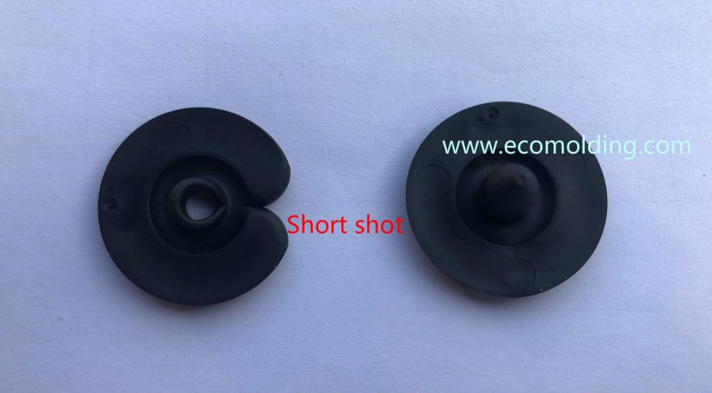
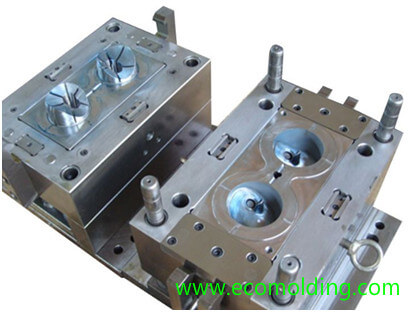
5. Each time before closing the mold, check whether the mold cavity is cleaned or not – no residual products or any other foreign objects are allowed. It is strictly forbidden to use hard tools to clean the cavity, so as to prevent the cavity surface from being damaged.

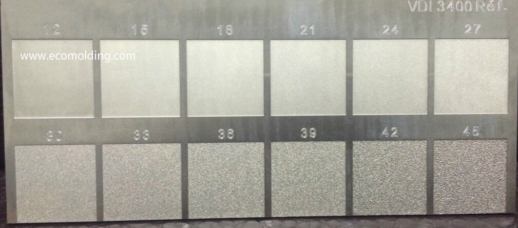
6. As for molds with special requirements for the cavity surface, the surface roughness (Ra) should be no higher than 0.2cm. It is absolutely not allowed to wipe it with hand or cotton fabrics. Instead, it should be cleaned with a compressed air blower, or gently wiped with high-grade alcohol napkins or absorbent cottons.

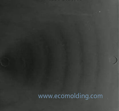
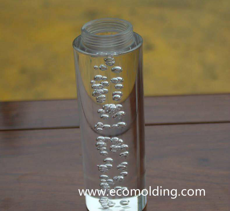
7. The cavity surface should be cleaned regularly. During the injection molding process, the mold will produce low molecular compound to corrode the mold cavity, so that the surface of the glossy cavity gradually becomes matted, thus affecting product quality. Therefore, it needs to be cleaned regularly by using alcohol or ketone preparation before being dried in a timely manner.

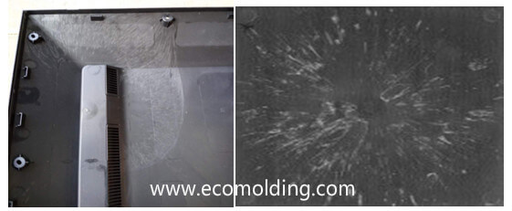
8. When the machine needs to be temporarily stopped, the mold should be closed to prevent the cavity and the core from being exposed, which might create accidental damage. If the downtime is expected to exceed 24 hours, the surface of the core and the cavity should be sprayed with anti-rust oil or release agent. Especially in moist areas and rainy seasons, they should be rust-proofed even if the downtime is very short. The moisture in the air will affect the surface quality of the cavity and the molded product. Before the mold is put into operation again, the oil on the mold should be removed and wiped clean. When cleaning a mold with mirror surface requirement, first use compressed air and then hot air to dry it, or the oil will be oozing out to cause product defect during the molding process.

What Causes Short Shot in Plastic Injection Molding?

short shot plastic injection molding defects

Short shot refers to incomplete filling of a mold cavity which results in the production of an incomplete part due to the insufficient plastic fluidity. The main causes are the inappropriate injection pressure and speed (including excessive pressure loss caused by resistance), which are mainly affected by the following aspects:

I. Injection Molding Machine:

(1) Insufficient injection molding capacity – This is caused by an overestimation of the capacity of the injection molding machine, which may also occur due to insufficient plasticizing capacity or insufficient injection volume. Among them, the insufficient plasticizing capability can be increased by extending the heating time, increasing the screw speed and raising the backpressure. If the injection volume is not high enough, the injection machine with a larger injection capacity can be used to solved the problem.

II. Inappropriate Mold Design

(1) Local short shot caused by the flow imbalance in each cavity of a multi-cavity mold – When the injection molding capacity of the injection molding machine is sufficient, this defect is mainly caused by the uneven flow in each gate, i.e., the mold cavities are not distributed in a balanced way.

(2) The flow range of the melt is too long, and the flow resistance is too large – The parts that hinder the flow of the melt include the nozzle, the sprue, the runner, the gate, and the thin walls of a product. The flow resistance of the nozzle can be reduced by increasing the nozzle diameter / temperature, and using a nozzle with a small flow resistance.

(3) Poor venting. When filling the cavity, air is trapped to cause counter pressure. When the melt is injected into the cavity, the cavity is often closed by the melt in the very beginning, with air trapped in the unfilled local areas. Also, because the filling speed is too fast, sometimes there is not enough time for the air to be vented through the parting surface but compressed instead, resulting in partial unfilled areas in the cavity, thus short shot in the molded part.

III. Improper Molding Process

(1) Improper injection molding process – The low barrel temperature, slow injection speed, short injection time, and insufficient backpressure lead to a shortage of plastic.

(2) Oversupply of plastic – If too much plastic enters the barrel, the injection pressure is lost due to the compression of the pellets, thus reducing the pressure required to inject the melt from the nozzle, which is necessary for injection molding, resulting in insufficient injection pressure. The solution is to adjust the amount of feed, i.e., the amount of melt, and make the amount just right for the molding.

(3) Unstable production cycle – Frequent machine shutdown, and production inconsistent with the normal cycle make some plastics stay in the barrel for too long with reduced density and viscosity, thus resulting in plastic underfill.

(4) Inappropriate mold temperature leads to lower injection speed and plastic underfill.

IV. Choice of Plastic

(1) Poor plastic fluidity – If the plastic material doesn’t feature a great fluidity, it will solidify before reaching the furthest end of the cavity or flowing to the overflow tank, which often results in a short shot.

In order to eliminate such defects, the melt / mold temperature, and the injection pressure / speed can be increased to allow the melt to reach the end of the cavity before solidifying. In such a case, a great plastic fluidity is of particular importance, so selecting the plastic with a better fluidity is also a solution. If the flow coverage is too long and the plastic cannot properly fill the injection molded part, it is recommended to change the gate location to reduce the plastic flow length.

(2) Try to evenly mix the recycled material and the raw material. Because the recycled pellets, as well as their density are relatively larger than the raw material, if the mixing is not uniform, the amount of the molten material is easily reduced, resulting in reduced injection volume accordingly.

V. Inappropriate Product Design

During the product design process, the principle of uniform wall thickness must be followed. If it is impossible to maintain a uniform wall thickness, please change the mold design in a timely manner. Increase the number of runners or ribs in the area where the feeding is difficult, so as to avoid the defect of underfill caused by too-thin wall thickness.

All in all, the reasons for short shot are multifaceted, which are also mutually restrictive and mutually influential. To reduce and correct such a defect, we need to make adjustments through an overall consideration of the relationship between these aspects, while making constant practice and accumulating experience continuously to quickly identify the causes of underfill, thereby reducing resource waste and improving product yield.

VDI 3400 Mold Texture and Drafting Angle

VDI 3400 texture for plastic injection mold

Bayer Plastics has some good Information about surfaces and injection molding available on their web- Site.
According to a (German) Document the VDI 3400 texture surfaces correspond to the following Ra / Rz Values and require the following drafting angles:

VDI3400RaRzDA-PADA-PCDA-ABS
120.40 1.50 0.5 1.0 0.5
150.56 2.40 0.5 1.0 0.5
180.80 3.30 0.5 1.0 0.5
211.12 4.70 0.5 1.0 0.5
241.60 6.50 0.5 1.5 1.0
272.24 10.50 1.0 2.0 1.5
303.15 12.50 1.5 2.0 2.0
334.50 17.50 2.0 3.0 2.5
366.30 24.00 2.5 4.0 3.0
399.00 34.00 3.0 5.0 4.0
4212.50 48.00 4.0 6.0 5.0
4518.00 69.00 5.0 7.0 6.0

DA-PA = Drafting Angle for Polyamide
DA-PC = Drafting Angle for Polycarbonate
DA-ABS = Drafting Angle for Acrilnitrile-Butadiene-Styrol

glass reinforced materials require more drafting.

VDI 3400 Table
In the following, you can determine the roughness for your application according to VDI 3400 table.

VDI3400  0-45µm µinchN3-N10ISO1302 Rt µm
00.10 4N3 
10.11 4.4  
20.12 4.8  
30.14 5.6  
40.16 6.4  
50.18 7.2N4 
60.20 8  
70.22 8.8  
80.25 10  
90.28 11.2  
100.32 12.8  
110.35 14N5 
120.40 16 1.6
130.45 18  
140.50 20  
150.56 22.4 3.2
160.63 25.2  
170.70 28  
180.80 32N65
190.90 36  
201.00 40  
211.12 44.8  
221.26 50.4  
231.40 56  
241.62 63 12
251.80 72N7 
262.00 80  
272.20 88 16
282.50 100  
292.80 112  
303.20 125N820
313.50 140  
324.00 160  
334.50 180 25
345.00 200  
355.60 224  
366.30 250N937
377.00 280  
388.00 320  
399.00 360 46
4010.00 400  
4111.20 448  
4212.60 500N1060
4314.00 560  
4416.00 640  
4518.00 760 85

What Causes Flow Lines in Plastic Injection Molding?

Definition of Flow Lines:                                               
Flow lines, also known as flow marks Linear marks on the surface of a molded product, which indicates the flow direction of the molten plastic.

flow lines marks

Injection Molding process

1.Insufficient Pressure / Holding Pressure                                               
The injection pressure and the holding pressure are not high enough to press the solidified layer against the mold surface, thus leaving flow lines along the melt flow direction.

Increase the injection pressure and the holding pressure, to press the solidified layer against the mold surface until the product is molded, so as to prevent the occurrence of flow lines.

2.Improper Residence Time                                      
The plastic material stays in the barrel for a too short period of time, while the melt temperature is low. Even if the cavity is barely filled, the plastic cannot be compacted during pressure holding, thus leaving flow lines along the melt flow direction.

The Shot-to-Barrel Ratio should be kept between 1/1.5 and 1/4.                                      
                                       
3.Improper Cycle Time                                      
When the cycle time is too short, the plastic is not sufficiently heated in the material barrel, and the temperature of the melt is low. Even though the cavity is barely filled, the plastic cannot be compacted during pressure holding, thus leaving flow lines along the melt flow direction

The cycle time is extended until the plastic is fully melted, and the temperature of the melt is high enough to prevent flow lines along the melt flow direction.                                      
                                       
4.Barrel Temperature Too Low                      

When the barrel temperature is too low, the melt temperature will be low, and the injection pressure and holding pressure will not be high enough to press the solidified layer against the mold surface, thus leaving flow lines along the melt flow direction.

Increase the material temperature, injection pressure and holding pressure to press the solidified layer against the mold surface until the product is molded, so as to prevent the occurrence of flow lines. The material temperature can be set by reference to material supplier’s recommendations.

The material barrel is divided into four zones: Rear, Center, Front and Nozzle. The material temperature settings should be gradually raised as it moves forward. Increase by 6°C with every zone forward.

When necessary, the temperature of the Nozzle and/or the Front are sometimes set to be the same as the Center temperature.                                       
                                       
5.Nozzle Temperature Too Low

After absorbing the heat released by the heating band, as well as the frictional heat generated by the relative movement of the plastic molecules caused by the rotation of the screw, the plastic in the barrel undergoes gradual temperature rises.

The last heating zone in the barrel is the Nozzle, where the melt should reach the desired temperature, but it must be moderately heated to maintain the optimal conditions.

If the nozzle temperature is not set high enough, due to too much heat is taken away through the contact between the nozzle and the mold, the material temperature will decrease, so that the injection pressure and the holding pressure will not be high enough to press the solidified layer against the mold surface, thus leaving flow lines along the melt flow direction.

Raise the Nozzle temperature. The nozzle temperature is usually set to be 6°C higher than the Front temperature.                                       
                                       
Mold                                       
1.Mold Temperature Too Low                                     
If the mold temperature is too low, the material temperature will drop very fast, so the injection pressure and the holding pressure will not be high enough to press the solidified layer against the mold surface, thus leaving flow lines along the melt flow direction.

Raise the mold temperature, maintain a high material temperature, as well as high injection pressure and holding pressure to press the solidified layer against the mold surface until the product is molded, so as to prevent the occurrence of flow lines.

The mold temperature can be set from the recommended values of the material supplier, with an increment of 6°C at each adjustment. Then perform 10 shots, and after the injection molding is stable, decide whether further adjustment is necessary according to the result.

2. Sizes of the Sprue, the Runner and/or the Gate

If the sprue, the runner, and/or the gate are too small, the flow resistance will be increased. And, if the injection pressure is not high enough, the advancement of the melt front will become slower and slower, and the plastic will become colder and colder, so that the insufficient injection pressure and holding pressure will not be able to press the solidified layer against the mold surface, thus leaving flow lines along the melt flow direction.

It is a feasible way to simulate and analyze the filling status of the different melt transfer systems (including the sprue, the runner and the gate) on a computer with CAE (such as, C-MOLD), to find out the ideal sprue, runner, and gate sizes (including length and section related dimensions, such as diameter, etc.) 

3. Insufficient Venting

Insufficient venting will cause the melt filling to be blocked, and the melt front will not be able to press the solidified layer against the mold surface, thus leaving flow lines along the melt flow direction.

Start venting at the end of each runner section, which removes a large amount of gas before filling the cavity.

The cavity venting should not be neglected. Consider adding vents on the parting surface opposite to the gate. Correspondingly, consider adding venting ejector pins at the end of the product blind hole.

Simulate melt filling through CAE (such as, C-MOLD), which helps us quickly find out all possible last filled areas, i.e., the areas where vents must be added. The addition of a vacuum system for air extracting before and during filling is an effective venting method.

For some textured products, this may be the only way of venting.                                      
                                       
Plastic Material

1.Poor Fluidity

The mold cavity with a large flow length to thickness ratio must be filled with the plastic that features great fluidity. If the fluidity of the plastic is not good enough, the melt will be flowing slower and slower, colder and colder, so that the injection pressure and the holding pressure are not high enough to press the solidified layer against the mold surface, thus leaving flow lines along the melt flow direction. Material suppliers are able to offer professional recommendations according to specific designs:

The most flowable plastic is selected on condition that no flashing is caused.

2.Improper Application of Molding Lubricant

Usually, the lubricant content is below 1%. When the flow length to wall thickness ratio is large, the lubricant content must be moderately increased to ensure that the solidified layer is pressed against the mold surface until the product is molded, so as to prevent the occurrence of flow lines. The lubricant must be increased upon agreement with the material supplier.

Operator

1. Bad Habits

Inconsistent molding result will occur if the operator switches the door of the injection molding machine too early or too late. When the barrel heater tries to replenish heat in time due to irregular heat loss, the plastic temperature will not be uniform, thus causing the cold spot. It is not easy for the injection pressure and the holding pressure to press the solidified layer around the cold spot against the mold surface, thus leaving flow lines along the melt flow direction. Usually, the operator should be constantly educated to let everyone know the troubles caused by inconsistent molding cycles and recognize the importance of maintaining best molding practices. Appropriate work shifts are able to prevent operators from making mistakes due to exhaustless or distraction. Automated production with robots or the like is a way to maintain a consistent molding cycle.

What causes silver streaks or marks during injection molding?

silver streaks,silver marks

Definition of silver Streaks:

Silver streaks are also referred to as silver marks, which appear like burst blisters on the surface of injection molded parts, mostly in the shape arrows pointing to the gate.

Causes of Silver Streaks:

I. Equipment

1. The nozzle hole is too small, the material leaks or draws at the nozzle, or the barrel or the nozzle is obstructed, and the material decomposes due to the frictional heat caused by high-speed melt flow;

2. The barrel and the screw wear, or melt flow dead ends exist in the screw cap and collar, which are decomposed due to long-time heating.

3. The heating system is out of control, causing the temperature to be too high and resulting in decomposition. Check whether there are any problems with the heating elements such as thermocouples and heating coils. Improper screw design also leads to decomposition or brings in air.

II. Mold

1. Due to design defects, such as poor gate location, too small gate, asymmetrical gate deployment, small runner, and improper mold cooling system, the mold temperature varies a lot, so the melt doesn’t flow smoothly in the cavity, which blocks the passage of air.

2. The corners are too sharp, and the shear force is too large when the melt passes by, thereby causing the occurrence of silver streaks; 

3. The mold parting surface is designed with no or insufficient vents, or the vents are blocked or inappropriately placed, with no clearances or gaps for venting, such as inserts and pins, so that the air in the cavity cannot be vented when the melt flows in. 

4. A rough mold surface creates a higher frictional resistance, causing local parts to be overheated, which decomposes the passing plastic.

5. The mold leaks oil, water, and air into the mold cavity, which easily causes silver streaks on the part surface.

III. Molding Process 

1. The material temperature is too high, which causes decomposition. If the barrel temperature is too high or the heating is imbalanced, the barrel temperature should be lowered step by step. If the temperature of the feeding section is too high, part of the plastic will melt prematurely and fill the groove, making it impossible to vent the air through the feeding port.

2. When the injection speed is too fast, the molten plastic will be decomposed by the large shear force, and gas is accordingly generated; if the injection speed is too slow, the product cannot be filled in time, causing an insufficient surface density, and thus the silver streaks.   

3. Insufficient material, too large feeding buffer, too low material temperature or too low mold temperature will affect the fluidity and molding pressure of the melt, and thus generate voids.

4. During pre-molding, if the screw backpressure is too low and the speed is too high, the screw will return too fast, so that the air is easily pushed to the front end of the barrel together with the material.

IV. Material

1. A large amount of dust is mixed into the raw materials or mixed with the pellets, which is easy to entrain air during the melting process, and sometimes silver streaks are caused. When the raw materials are contaminated or there is too much dust, the raw materials are easily decomposed when being heated.

2. Too much sprue (recycled material) is added, the sprue is recycled for too many times, or a too high proportion of sprue is mixed with the new material (usually no higher than 20%).

3. The additives in the material decompose to generate silver streaks.

4. Excessively moist materials are not fully dried, resulting in silver streaks.

5. The material contains a high water content or is porous, which causes the silver streaks on the molded part.

What causes air bubbles or voids in injection molding?

air bubbles injection molding defects

According to the cause of air bubbles or vacuum voids , the solutions to the defects are described as below:

(1) When the wall thickness of the product is large, the outer surface is cooled down faster than the center portion. Therefore, as the cooling progresses, the resin at the center portion is expanded toward the surface while shrinking, so that the center portion is insufficiently filled. This situation is referred to as air bubbles, to which the main solutions are:

a) Determine the proper gate and runner size based on wall thickness. Generally, the height of the gate should be 50%-60% of the product wall thickness.

b) A certain amount of supplementary injection material is retained until the gate is sealed.

c) The injection time should be slightly longer than the gate sealing time.

d) Lower the injection speed and increase the injection pressure

e) Select a material with a higher melt viscosity.

(2) The air bubbles caused by volatile gases are mainly solved by:

a) Sufficient pre-drying.

b) Lowering the resin temperature to avoid gases caused by decomposition.

(3) Air bubbles caused by poor fluidity can be solved by raising the resin / mold temperature and increasing the injection speed.

PC/ABS injection molding defects and solutions

Seven Common Defects and Solutions for PC/ABS injection molding Products

PC/ABS injection molding defects

Flow Lines

The flow lines are caused due to the poor fluidity of the material. Unlike silver streaks, it is not caused by moisture or material decomposition, thus resulting in a different look.

Solution: The flow lines can be eliminated by raising the material temperature so as to improve the fluidity. Appropriate increase of mold temperature and decrease of injection speed can also solve the problem.

 Pitting

The shrinkage cavities are caused by short shot in the mold cavity.

Solution: Increase mold temperature and material temperature appropriately to improve material fluidity; extend the injection / pressure holding time, and raise the injection speed to improve the mold filling, or increase the size of the gate and heat the sprue to reduce and eliminate the shrinkage cavities on the products.

If the product is not appropriately designed and the material temperature is too low, not only the shrinkage cavities, but also pitting will occur. If the material temperature and the mold temperature are too high, the melt will shrink excessively during cooling, resulting in pitting.

Solution: Appropriately increase the injection speed.


Warpage / Deformation 

Solution: 

The warpage / deformation of PC/ABS injection molding product is caused by the unreasonable product design, the improper gate location and the inappropriate conditions of the injection molding process, so that the stress is generated inside, leading to the ununiform or excessive shrinkage. If the mold temperature is too high or uneven, it will cause the difficult product ejection, or ununiform cooling, which will also lead to warpage / deformation.

Solution:

Molding Process: Extend the injection molding cycle, lower the injection molding temperature, appropriately adjust the injection pressure and the injection speed, reduce the ejection speed, increase the ejection area, and balance the ejector force.

Product Design: Increase product wall thickness, add ribs and fillet reinforcements to reduce warpage / deformation.

Silver Streaks

Silver streaks are the most common defects with the PC/ABS injection molding material, which refers to the appearance of the silvery-white silk-like stripes on the surface of the molded product along the flow direction.

The main cause is the interference of gas, which is mainly comprised of three components:

Air: The air drawn in during the melting and injection stages;

Moisture: The moisture contained in the material itself;

Pyrolysis Gas: Gas generated by high temperature hydrolysis / thermal decomposition.

Solution: First of all, check whether the material is fully dried; after the material is confirmed to be dry, the silver streak defect can be improved by adjusting the injection molding process. At the same time, this defect is also correlated to mold venting.

Matting

Solution:

Poor dispersion: add dispersant or oil, raise temperature, and increase backpressure.

Pay attention to the mold problem. Try some other materials.

Whether the injection temperature and time are sufficient.

Adjust the mold temperature.

Product Delamination

The delamination defect of PC/ABS injection molding products is closely related to the rupture of the melt caused by high shear force. Under low shear stress or velocity conditions, small disturbances caused by various factors are suppressed by the melt, while at high shear stress or velocity, disturbances in the melt are difficult to suppress and thus develop into an unstable flow;

When a critical shear force is reached, the fracture of the fluid will be caused.

Solution:

Material: The two components of PC and ABS are partially compatible, so it is necessary to add proper compatibilizer to improve the compatibility of the two components in the process of modification. Of course, the first thing to do is to eliminate the delamination caused by the mixture.

Mold: The principle of mold design should follow the direction of minimizing shear. Generally speaking, products with densely striped surfaces are more prone to delamination (caused by the friction shear between melt and inner wall of cavity during high-speed filling). At the same time, the gate size designed too small will lead to excessive shear when the melt is flowing through the gate, and then lead to product surface delamination.

Injection Molding Process: The main purpose is to avoid excessive shear. The high-speed & high-pressure injection can be used to improve the product filling difficulty, and therefore, in the actual injection molding process, the flow resistance in the actual filling process can be reduced, so as to avoid excessive shear caused by high-speed and high-pressure injection molding process

Stretch Marks

Stretch marks usually occur due to melt rupture when the melt expands into the mold cavity during high-speed injection.

Solution:

Molding Process: This defect can be reduced by raising the material temperature and the nozzle temperature, and slowing down the injection speed, etc.

How to Control the Dimensions Tolerance of Injection Molding Products

Due to the greatly varied market demands for molds and molded products, there are many kinds of changes and thus high requirements for us in such aspects as shape, size, material, structure and more, causing us many problems and difficulties in the production process of molds and products. How to effectively control the geometric dimensions of the mold and the product is just one of them.

injection molding dimensions control

For different types of molds and products, there are different control techniques and methods for dimensions control. Personally, I usually start from the following aspects.

Mold Design Control

Firstly, we have to fully understand the technical requirements for the mold structure, material, hardness, and precision, etc., including whether the shrinkage rate of the plastic material is proper, and whether the 3D model of the product is complete, in a bid to perform reasonable analysis.

2. Thorough consideration should be given to various factors that may influence the product appearance, including shrinkage, flow marks, draft angle, weld lines and cracks of the injection molded product.

3. Try to simplify the processing method of the mold without impeding the function, shape and texture of the injection molded product.

4. Whether the selection of the parting surface is appropriate; the mold machining, product appearance and deburring of the molded part should be carefully considered.

5. Is the ejection method appropriate; use the ejector pin, the stripper plate, the ejector sleeve or other methods; whether the ejector pin and stripper plate are appropriately located.

6. What temperature control method is suitable for the plastic part; which circulation system structure is suitable for temperature control oil, temperature control water, or coolant, etc.; whether the size, quantity and location of the coolant holes are appropriate.

8. Whether the type of the gate, the size of the runner and the gate, as well as the location of the gate are appropriate.

7. Whether the injection volume, the injection pressure and the clamping force of the injection molding machine are sufficient; whether the nozzle R, and the nozzle sleeve diameter, etc. match properly.

Perform comprehensive analysis and make preparation from all of these aspects, to strictly control the product from the very beginning.

Manufacturing Process Control

Although comprehensive consideration and arrangement have been carried out in the design stage, there are still many problems and difficulties during the actual production process. We should try our best to meet the original intention of the design and find the most effective and most economical processing method in actual production.

1. Choose the economical machine tools for 2D and 3D processing.

2. We should also consider a string of production process requirements and solutions, e.g., the appropriate fixtures to facilitate preparation for production, and the rational application of cutters, so as to prevent product deformation, avoid fluctuations in product shrinkage, and eliminate product warpage caused during ejection, thus improving the precision of mold manufacturing, minimizing errors and preventing mold accuracy changes, etc.

3. Here, I’d like to mention a summary of the reasons for the dimensional error and the corresponding proportion, drafted by the British Plastics Federation (BPF):

A: The mold manufacturing error is about 1/3 for dimensions control; B: The error caused by mold tear and wear is 1/6; C: The error caused by the uneven shrinkage of the molded part is about 1/3 for dimensions control; D: The error caused by the difference between the preset shrinkage and the actual shrinkage is 1/6.

Total error = A + B + C + D, so we can see that the mold manufacturing tolerance should be kept within 1/3 of the dimensional tolerance of the molded part, otherwise it is difficult for the mold to guarantee the geometric dimensions control of the molded part.

 General Production Control

It is a common problem and phenomenon that geometric fluctuations occur after the plastic part is molded:

1. Control of material temperature and mold temperature. Different plastic materials have different requirements for temperature. Different situations will occur if the plastic features a poor fluidity or two materials are mixed. The plastic should be controlled within the optimal fluidity range, which is easy to achieve. However, the control of the mold temperature is more complicated. Different geometry, size and wall thickness of the molded product have certain requirements for the cooling system. The length of the cooling time is largely dependent on the mold temperature.

Therefore, the mold should be kept at an allowable as low as possible temperature, so as to shorten the injection cycle, and improve production efficiency. If the mold temperature changes, the shrinkage rate also changes; if the mold temperature remains stable, then the dimensional accuracy is stabilized, thereby preventing such defects of the molded part as deformation, poor glossiness, etc., and ensuring the optimal physical properties of the plastic. Of course, there is a commissioning process. In particular, the injection molding of multi-cavity molds is more complicated.

2. Pressure & Venting Control:

The proper injection pressure and clamping force should be determined when the mold is being commissioned. The air in the mold cavity and the core, and the gas generated by the plastic must be vented through the mold vents. If the gas is not smoothly vented, there will be the three molding defects of underfilling, weld marks or burns, which sometimes appear on the same part. However, as long as flashing doesn’t occur, the depth of the vents should be as deep as possible. Behind the shoulder, larger venting grooves are usually designed for the gas to vent through the shoulder quickly. If needed, a special venting groove can be designed on the ejector pin, for which the reason is the same, i.e., 1. No flashing occurs; 2. The venting is fast and effective.

3. Plastic Part Dimensional Compensation Control

Due to the difference in the shape and size of some plastic parts, deformation and warpage may occur in different situations with the change of temperature and loss of pressure after product ejection. At this time, some assistive fixtures can be used to make remedies for dimensions control in a timely manner after the molded part is released, so that when the product is naturally cooled and shaped, better adjustment and remedy results can be obtained. If strict management is ensured throughout the injection molding process, the dimensions of the injection molded part can be very well controlled.

PVC injection molding plastic resin

PVC plastic is a heat-sensitive material that features a poor injection moldability, for which the reason is that an excessively high melt temperature or an excessively long heating time easily causes PVC decomposition. Therefore, the key to molding the PVC products lies in the control of the melting temperature.
PVC injection molding plastic resin

The heat sources for melting the raw PVC material are usually from two aspects, i.e., the shear heating generated by screw motion and the resistance wire heating provided by the outer wall of the barrel, among which, the former is the main source, while the latter is mostly provided during machine operation.

Due to the unsatisfactory heat transfer property of the PVC material, although the outer portion is heated, the inner portion of the material is still in a solid state, and even when the outer portion starts to decompose due to overheating, there may still be an unmolten portion inside. Various reasons must be fully considered during product design, mold design, and the plastic injection molding process, etc. In particular, the special PVC injection molding machine from outstanding manufacturers can be selected to create the ideal product.

The following are the considerations that should be attached great importance to during the injection molding process of PVC, in the hope of helping the readers.

1.Pay attention to the following points during product design and mold design:
Try to avoid sharp corners or abrupt changes in the product, and the thickness should not change too much, so as to prevent the PVC from degrading.

2.The mold should be designed with a draft angle of more than 10°, allowing for a shrinkage rate of about 0.5%.

3.During mold runner design, pay attention to the following points

a). The mold injection gate should be slightly larger than the nozzle, and larger than the diameter of the conjunctions in the sprue, so that the PVC material is able to flow into the cavity without being blocked, while the pressure is also balanced.
b). Try to adopt the intercepting gate, so that the slag will not flow into the product and cause runner temperature reduction, thus making it easier to form.

c). The gate should be designed at the thickest part of the product, with a sufficient width guaranteed, while the length is preferably between 6-8mm, so that the PVC material is able to flow in smoothly.

d). To reduce pressure and facilitate ejection, a circular runner is preferred, with the diameter ranging from 6 to 10mm, depending on the size and weight of the product.

4. The mold temperature should be controlled by a cooling device, to keep the temperature controllable between 30°C and 60°C.

5.The mold surface should be smooth and chrome-plated to prevent corrosion.

PVC injection molding process

With regard to the injection molding process, pay attention to the following:

PVC injection molded product

  • The backpressure should be kept at about 1Mpa, because excessively high backpressure will produce excessive shear force, which will cause the PVC to decompose. At the same time, the multi-stage backpressure control should be adopted in the melting process. In the beginning when the effective length of the screw is long, the backpressure should be kept low. As the effective length of the screw decreases, the backpressure should be appropriately increased to compensate for the heat loss. Shortly before material recycling ends, the backpressure should be lowered to prevent leakage.
  • The screw speed should vary according to the diameter. Usually, when the diameter is < 60mm, the speed is 50-70rpm; when the diameter is > 70mm, the speed is 20-50rpm, so as to prevent excessive shearing and PVC degradation.
  • Usually, to inject the plastic into the cavity with a uniform speed throughout the process, the multi-stage injection speed control is adopted, of which the principle is to start with a low speed, and as the molding area increases, the injection speed must be increased to avoid cracks and shrinkage marks. The injection speed cannot be so fast, or the product surface will be denuded.
  • During the plastic injection molding process, the barrel temperature should be kept between 170-190°C. To prevent the PVC from overheating and degrading, when the temperature of the barrel reaches the set temperature, the blower should be started to cool the temperature down. On the contrary, when the temperature needs to be raised, the air blower should be shut down.

Due to the special properties of the PVC material, special PVC injection molding machines should be selected for production. Please note the following points:

  • The screw length to diameter ratio should be 20:1, and the compression ratio should be controlled between 1:1.6 and 1:1.2.
  • The screw and nozzle should be specially made and chrome-plated for the PVC material.
  • Injection pressure, speed, backpressure and temperature can be multi-stage and precision controlled. (The four-cylinder direct-lock two-plate PVC injection molding machine we produce possesses the above-mentioned performances, and we look forward to your inquiry)

Last but not the least, the following requirements should be noted in the preparation of raw materials:

  • It is necessary to prevent the raw PVC material from being mixed with other plastics, or PVC degradation might be caused. Especially, when the machine has worked with other raw materials, it is necessary to clean the barrel and the screw before molding the PVC product. (Clean the screw and barrel with the PS plastic)
  • Before shutdown, the PVC material must be completely cleaned. If it needs to be stopped for a long time, to prevent the PVC from corroding the machine, the screw and the barrel should be cleaned with PS.
  • When the PVC injection molding material is put away for more than 6 months in a hot and humid environment, it should be dried for 1-2 hours under the 60-80°C temperature conditions before use.

Mold steels P20,718 and H13 comparison

Mold steel p20,H13

P20 Mold steel

Overview:The P20 Mold Steel is a type of mold welding consumable, and the earliest is P20, followed by P20H and P20Ni. The P20 Steel is applicable to the production of molds for plastic materials, as well as those for diecasting low melting point metals. This steel material features great machinability, as well as mirror polishing properties.

Chemical composition

Element C Si Mn Mo Cr Ni
(%) 0.28~0.40 0.20~0.80 0.60~1.00 0.30~0.55 1.40~2.00 0.80~1.20


How to Use: The P20 Steel is pre-hardened to 285-330HB (30-36HRC), which is equivalent to 618 of Sweden and GS-2311 of Germany. It can be directly used for molding, and boasts a great dimensional stability. Pre-hardened steel is able to meet the requirements for general applications, with a mold service life of up to 500,000 cycles.

Characteristics

  • The vacuum degassing process ensures the purity of the steel, making it suitable for plastic molds that require polishing or etching treatment.
  • Supplied as a pre-hardened steel, able to be directly used for mold manufacturing without having to be heated, thus reducing the production cycle.
  • After forging and rolling, the structure is dense, and no pores or pinholes are found according to 100% ultrasonic inspection.


Purposes

  • Injection molds, and extrusion dies for thermoplastics
  • Blow molds for thermoplastics
  • Main parts for heavy duty molds
  • Parts for cold insulation structure
  • Commonly used in the production of TV casings, inner shell of washing machine / refrigerator, and buckets, etc.


718 Steel

Overview

The 718 Mold Steel, known as 3Cr2NiMo in China, is an enhanced steel on the basis of P20 (3Cr2Mo). The quality of the steel material has been so greatly improved that it is able to compensate for the weaknesses of the P20 Mold Steel, and at the same time meet the requirements that are beyond P20. Among today’s mold steel materials in China, there is also P20+Ni, in addition to the above-mentioned Chinese standard steel grades. The 718 and 718H (ASSAB) from Sweden; the PX5/PX4 (DAIDO Special Steel, Japan); the GS-711, GS-738, GS-312 and GS-318 (Thyssen, Germany); and the M238 ECOPLUS (BOHLER) from Austria are the most widely used general-purpose mold steel grades for molding plastic materials. It is often referred to as an “advanced” plastic mold steel that always serves as a benchmark for newly developed mold steels.

Purposes

The purpose of the 718 Mold Steel is the same as that of the P20 Mold Steel, but by virtue of its better hardenability and superior performance, it is able to be used for production of the forming parts of large-sized and high-end plastic molds.

  • Injection molds, and extrusion dies for thermoplastics
  • Blow molds for thermoplastics
  • Main parts for heavy duty molds
  • Parts for cold insulation structure
  • Commonly used in the production of TV casings, inner shell of washing machine / refrigerator, and buckets, etc.
  • The vacuum degassing process ensures the purity of the steel, making it suitable for plastic molds that require polishing or etching treatment.
  • Supplied as a pre-hardened steel, able to be directly used for mold manufacturing without having to be heated, thus reducing the production cycle.
  • After forging and rolling, the structure is dense, and no pores or pinholes are found according to 100% ultrasonic inspection.


Chemical composition

Element C Si Mn Mo Cr Ni
(%) 0.28~0.40 0.20~0.80 0.60~1.00 0.30~0.55 1.40~2.00 0.80~1.20

Hardening

In order to improve the mold service life to more than 800,000 molding cycles, the pre-hardened steel can be further hardened by quenching and low temperature tempering. Before quenching, pre-heat the steel under 500-600°C temperature conditions for 2-4 hours, then keep the temperature at 850-880°C for a certain period of time (at least 2 hours), oil-cool it to 50-100°C, followed by air cooling, and the hardness can reach up to 50-52HRC after quenching. To prevent cracking, immediately perform low-temperature tempering at 200 °C, after which, the hardness can be kept over 48HRC.

Nitriding

Nitriding helps obtain a high-hardness surface structure, after which, the surface hardness can reach up to 650-700HV (57-60HRC), and the service life of the mold is able to exceed 1 million cycles. The nitrided layer features a compact structure and smoothness, with improved ejection performance, as well as resistance to moisture and alkaline solutions.


Steel H13

Overview

mold steel H13

H13 is a hot work steel, and the grade is 4Cr5MoSiV1; an alloy tool steel is formed by adding alloying elements on the basis of the carbon steel. Among them, the alloy tool steels include: measuring and cutting tool steels, steel for impact resistant tools, cold work mold steel, hot work mold metal, non-magnetic mold steels, and plastic mold steels.

Chemical composition

Element C Si Mn Cr Mo V P S
(%) 0.32~0.45 0.80~1.20 0.20~0.50 4.75~5.50 1.10~1.75 0.80~1.20 0.030 0.03

Heating

After heat treatment, the top hardness of the H13 mold Steel reaches up to HRC52. When the minimum size of a part is greater than 300mm, the hardness after heating should be kept within HRC50.

Characteristics

As an electroslag heavy-duty steel, it boasts high hardenability and thermal crack resistance. The steel contains a high content of carbon and vanadium, allowing it to have a great wear resistance, but a relatively weaker toughness. Other features include great heat resistance, outstanding strength and hardness at high temperatures, as well as high wear resistance and toughness, excellent mechanical properties and high resistance to tempering.

Other designations that are equivalent to H13 Mold steels include:

  • AFNOR Z 40 COV 5
  • DIN 1.2344
  • UNI KU
  • JIS SKD61
  • SS 2242
  • B.S. BH 13
  • ASTM A681
  • FED QQ-T-570
  • SAE J437
  • SAE J438
  • SAE J467
  • UNS T20813
  • AMS 6408

Purposes

It is used for the production of forging dies with a high impact load, hot extrusion dies, precision forging dies; as well as die-casting molds for aluminum, copper and their alloys.