Warpage injection molding defects causes and solutions

Warpage as one of the most common defects in a plastic injection molded product, refers to the situation in which the shape of the injection molded part deviates from the shape of the mold cavity. The following is a brief analysis of the factors that affect the warpage of the injection molded products.

warpage injection molding defects

How the mold structure influences the warpage of an injection molded product

With regard to the mold, the main factors that affect the deformation of a plastic part are the gating system, the cooling system and the ejection system

Gating System

The gate location, type and quantity of a plastic injection mold affect the filling status of the plastic in the mold cavity, leading to changes to the plastic part. For some flat plastic parts, if only one central gate is employed, the molded plastic part will be distorted, as the shrinkage rate along the diameter is greater than that along the circumference; if multiple pin-point gates or the film gate is used, product warpage defects can be effectively prevented.

Cooling System

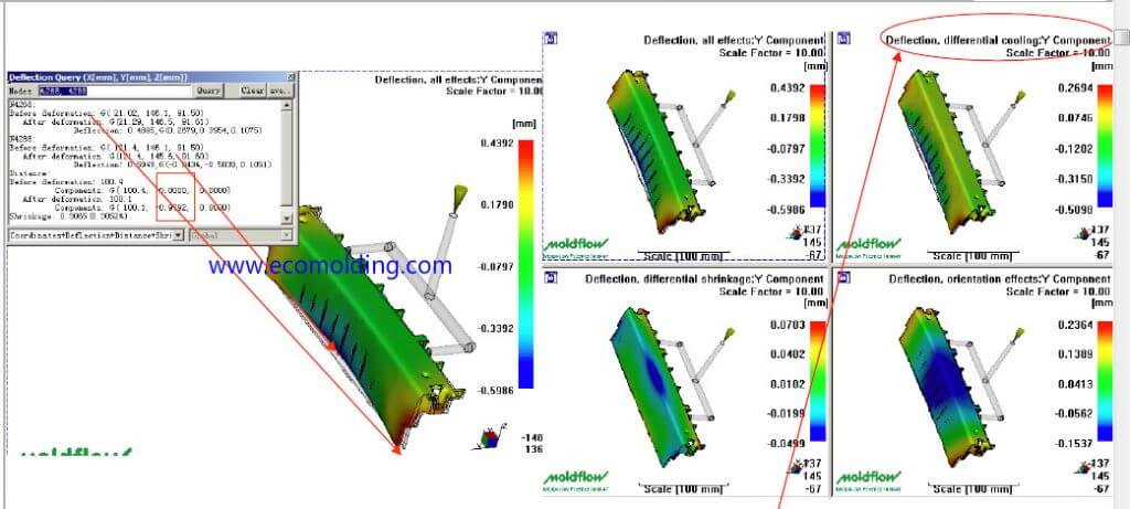
During the plastic injection molding process, the ununiform cooling rate of the plastic part will also cause ununiform shrinkage in the part, which leads to the generation of the bending moment, and therefore warpage of the plastic injection molded part.

During the plastic injection molding of a flat plastic part (such as the mobile phone battery case), if the temperatures in the mold cavity and the core differ greatly, the molten plastic close to the surface of the cold mold body is quickly cooled down, and that close to the surface of the hot mold cavity continues to shrink. Such an ununiform shrinkage will cause part warpage. In addition to considering the temperature balance inside and outside the plastic part, it also needs to be ensured that the temperature on each side of the plastic part is consistent, i.e., during mold cooling, the temperatures of mold core and the mold cavity should be kept as consistent and uniform as possible, so that an uniform cooling rate throughout the plastic part is ensured to effectively prevent the occurrence of warpage.

Ejection System

The design of the ejection system also directly affects the warpage of a plastic injection molded part. If the ejection system is not designed with a balanced layout, it will cause an imbalance in the ejection force, which leads to plastic product warpage. The cross-sectional area of the ejector pin should not be too small, so as to prevent the plastic part from being deformed by excessive force per unit area (especially when the temperature is too high during ejection). The ejector pins should be placed as close as possible to the area with a large ejection resistance.

How plasticization process influences product warpage

Plasticization refers to the process in which the plastic is converted from vitreous granules into a viscous melt. During this process, the temperature differences of the polymer along the axial and the radial directions (relative to the screw) will cause stress in the plastic material; in addition, the injection pressure, speed and other parameters of the injection molding machine have a great impact on the degree of molecular orientation during plastic filling, which causes warpage, or deformation.

How plastic filling and cooling influence product warpage

cooling factors for warpage

The effect of temperature on product warpage is reflected in the following aspects:

  • The temperature difference between the upper and lower surfaces of the plastic part may cause thermal stress and therefore thermal deformation;
  • The temperature difference between different areas of the plastic part will cause uneven shrinkage between different areas;
  • Different temperature conditions influence the shrinkage of a plastic part.

How product ejection influences product warpage

The imbalanced ejection force, unsteadiness in the movement of the ejection mechanism, or the inappropriately designed ejection area easily causes product deformation . At the same time, the stress that is “frozen” in the plastic part during the filling and cooling processes will be released in the form of “warpage” due to the loss of external constraints, resulting in product deformation.

How product shrinkage influences product warpage

The immediate cause of warpage defects of an injection molded product is the uneven shrinkage of the product. If the influence of shrinkage during the filling process is not taken into consideration during the mold design stage, the geometry of the product will vary greatly from the design requirements. For warpage analysis, shrinkage itself is not important, but what is important lies in the shrinkage difference.

How residual thermal stress influences product warpage

During the plastic injection molding process, residual thermal stress is an important factor that causes product warpage, and thus exerts a great influence on the quality of an injection molded product. Since the influence of residual thermal stress on product warpage is very complicated, it will not be detailed here.

How the metal insert influences product warpage

With regard to plastic injection molded products with inserts, it is easy to cause distortion (even cracking), since the shrinkage of plastic is much higher than that of metal; to improve this, the metal part needs be preheated (generally at a temperature of no lower than 100°C), before being put into production.

Conclusion

There are many factors that affect the warpage defects of an injection molded product. The structure of the mold, the thermophysical properties of the plastic material, as well as the conditions and parameters of the molding process all exert different influences on the product warpage defects. Therefore, when handling the warpage of a molded product, we must take all the above factors into consideration.

Methods for Coloring Plastics resin

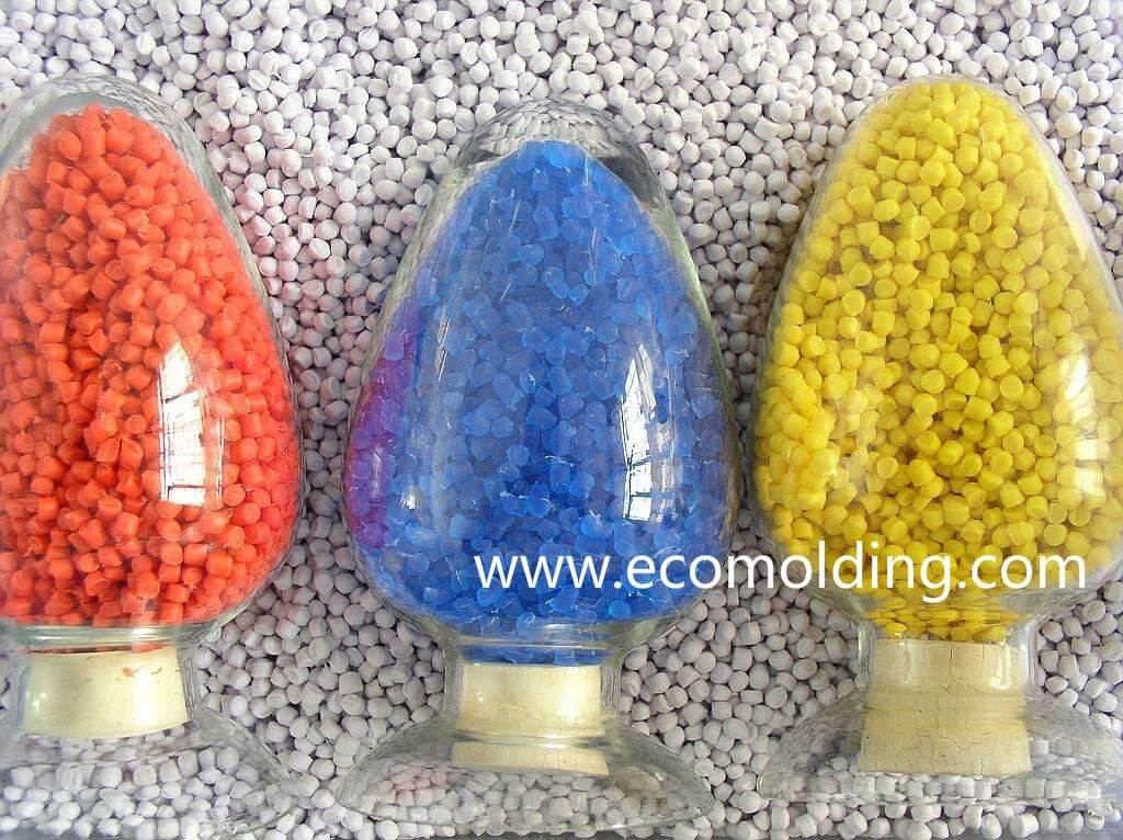
A variety of plastics coloring systems can be used to get color for the plastic materials, each possessing its unique features, benefits, and weaknesses.now we share some plastics coloring process as below:

Select a Color Scheme

According to the plastic properties, the molding process, the toner characteristics, the color matching principles, the product requirements and other comprehensive considerations, match the various toners, and then achieve the required color requirements. Each color has a certain hue, a certain brightness, and a certain degree of saturation, so you can call up tens of thousands of different colors by changing these three factors. Therefore, during toning, it is the most basic technique to adjust the three factors of depth, hue and difference. The toning principle requires us to adjust the depth first and then the hue, because when the depth changes, the hue will definitely change.

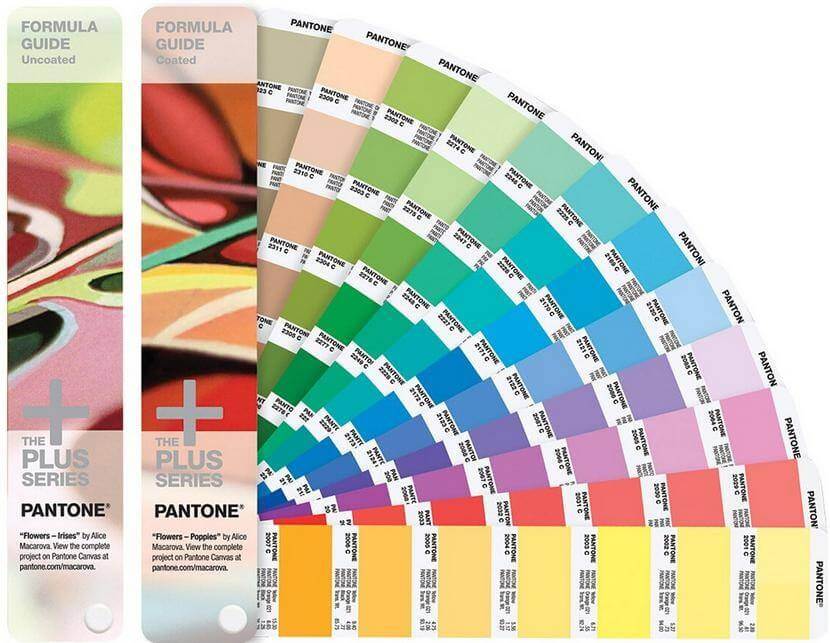
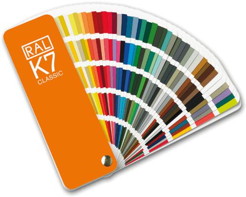
The most porpular color matching systems include Panotone and RAL,please click below links for detail:

PANTONE-color chart

Pantone color chart

RAL Color Chart

coloring plastics

We always use this two systems to coloring plastics resin.

Adjust the Depth

According to the target sample, observe the degree of penetration and the depth of the hue, to determine the proportion of black and white in the composition; or for colors other than black and white, determine the color toner concentration or the proportion of the fluorescent toner in the color. The tinting strength of the toner can be identified by using various toners on the same plastic substrate. For instance, the PP material is added with 20g, 50g, 100g, or 300g, etc., to sufficiently determine its coloring degree. At the same time, we must understand the color change and concentration change of each color pigment after a certain proportion of titanium dioxide is added. In the process of coloring plastics, it needs to be clear whether the color is deep or dark in the depth direction. If it is deep, the hue can only be added with the toner. If it is dark, the toner can be added with the black color. Of course, a small amount of black can be added to increase the depth of a dark phase. In the shallow direction, the amount of titanium dioxide should be determined according to the degree of solid color. If it is not solid enough, it needs to be added with more titanium dioxide. In the meantime, other toners should be added in proportion, then estimate the proportion of colorants according to the shade of the hue and the tinting strength of various colorants.

Adjust the Hue

Theoretically, most of the colors can be matched with the mixture of the three primary colors of red, yellow and blue, but in fact, the colors of the various colorants are not simple colors but in between them, with the shade of the adjacent color. For example, the red toner contains yellowish red and blueish red, the blue toner contains reddish blue and greenish blue, and the yellow toner contains greenish yellow and reddish yellow. In the process of toning, pay attention to the complementarity of shades. For example, when the color is bright green, you can use the indigo green directly. If you need a darker green, you should choose greenish blue and greenish yellow to match the color, but not with the complementary reddish blue and greenish yellow.

Adjust the Difference

After estimating the depth and hue, the basic formula can be determined. After sampling, check the sample against the standard color, and then perform color difference correction. The color difference is related to the deviation of the depth, vividness, brightness, and hue. First of all, we need to determine what has caused the color difference – use the black and white toner to adjust the shade, and add a proper amount of toner, fluorescent power or whitening agent to adjust the vividness and brightness, while the hue can be adjusted by increasing or decreasing the amount of the toner or adjustment of the complementary colors, but be aware that the complementary colors may darken the color.

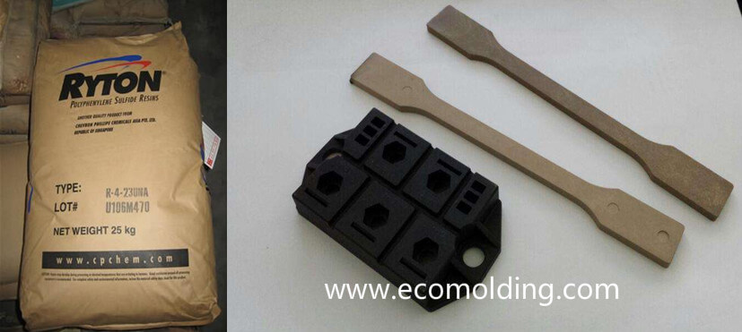
PPS injection molding plastic resin

Poly phenylene sulfide, abbreviated as PPS, is a new type of engineering plastic, which is mainly divided into two categories: one is a branched thermoplastic polymer with a high viscosity, and the other is a thermosetting polymer which has a linear molecular structure before curing, and can be softened to a certain extent if sufficiently heated after curing. In the following, we will mainly introduce the thermosetting PPS.

PPS plastic injection molding

The Properties of PPS

  1. Physical Properties

PPS is a white, highly crystalline polymer with a density of 1.34. It is characterized by excellent mechanical properties, with tensile strength and flexural strength superior to that of PA, PC, and PBT, etc. It possesses extremely high rigidity and resistance to creep, but high brittleness and low notched impact strength that is even lower than that of PA, PC and PBT, but higher than that of POM. After being reinforced by glass fiber, better mechanical properties can be obtained. PPS is an inert and non-toxic substance.

  1. Thermal Properties

Since PPS is a crystalline polymer, the highest crystallinity can reach up to 65%, its crystallization temperature is 127°C, melting point is 286°C, and the heat distortion temperature is 260°C. With a thermal stability far exceeding that of such engineering plastics as PA, PBT and POM, it only decomposes when the air temperature reaches above 430-460°C, so its long-term application temperature is the highest among all thermoplastics, reaching up to 220-240°C. PPS also has great thermal insulation and flame retardancy performances. Its critical oxygen index is equivalent to that of PVC, up to 47%, so there is no need to add flame retardant, because PPS is able to reach the UL94 V-0 flammability rating.

  1. Electrical Properties

PPS has a symmetrical molecular structure, no polarity and a low water absorption rate, so it boasts an excellent electrical insulation performance. Compared with other engineering plastics, its dielectric constant is low, and its arc resistance is equivalent to that of thermosetting plastics. Under such conditions as high temperature, high humidity and frequency conversion, PPS can still maintain outstanding electrical insulation. Conductive PPS composites can be obtained by adding conductive fillers for antistatic and electromagnetic shielding effects.

  1. Chemical Resistance

It is insoluble in any organic solvent below 200°C. It is able to withstand the erosion of all kinds of acids, alkalis and salts, except the strong oxidizing acid. It still maintains a high strength after long-term immersion in various chemicals under high temperature conditions. PPS also boasts great weatherability and resistance to radiation.

PPS Injection Molding Processability

1). Water Absorption

PPS features a low water absorption of only 0.02%.

2). Fluidity

With great fluidity, PPS can be used to make thin-walled products. However, if the temperature is too high or the material stays in the barrel for too long, the material will partially crosslink, resulting in a low fluidity.

3). Crystallinity

PPS is a crystalline polymer, of which the crystallinity varies depending on the cooling temperature and rate during the plastic injection molding process. The faster the cooling rate, the lower the crystallinity. The degree of crystallinity has a great influence on its strength, thermal resistance, weatherability and dimensional stability. As the degree of crystallinity increases, the heat deflection temperature (HDT) of the product rises, with increased rigidity, surface glossiness, surface shrinkage, and dimensional stability.

4). Thermal Stability

PPS will undergo partial oxidation and crosslinking reaction if exposed to high temperature conditions for a long time, resulting in a decreased fluidity and a deeper color of the material, which will affect the quality and performance of the product. In addition, PPS is strongly adhesive to metals, so it is necessary to prevent the material from solidifying in the barrel.

5). Shrinkage

For the crystalline plastics, the crystallinity increases as the mold temperature increases during the plastic injection molding process, while the shrinkage rate increases with the increase of crystallinity. Therefore, the shrinkage increases with the rise of mold temperature. Generally speaking, the shrinkage rate of PPS is low, but the shrinkage perpendicular to the flow direction is 2-4 times higher than that in the flow direction. Product thickness, shape, and injection speed also the factors that influence the shrinkage rate.

6). Secondary Processing

PPS products can be processed by machining, ultrasonic welding, adhesive bonding, etc., such as cutting and tapping.

Molding Preparation: Conventional injection molding machines can all be used for PPS processing. It is recommended to use wear-resistant barrels, screws and molds that are suitable for such fillers as fiberglass and minerals.

Drying Preparation: Although PPS absorbs very little water in a humid environment, drying is necessary if you want to get high quality products. Please refer to the following drying conditions:

120℃: 4-6 hours

130℃: 3-5 hours

140℃: 2-3 hours

If the drying temperature is too high or the drying time is too long, the color or fluidity of the raw material may change.  The melting point of PPS is 280°C, so the barrel temperature of 300-340°C is the most commonly used for most applications.

Mold Temperature

The mold surface temperature should be no lower than 120°C. Usually, 130-150°C is recommended. Higher mold temperatures ensure a high degree of crystallization, a smooth product surface and reduced shrinkage after molding. If a lower mold temperature is required in special circumstances, you should try to avoid the temperature range of 80-100°C, which may cause the vitrification of PPS, thus making it hard for ejection.

Injection Speed

To prevent melt cooling / curing during the injection process, a higher injection speed is necessary. The optimal product appearance is usually obtained at an appropriate speed. The filling time is usually 0.5-1.5 seconds, but excessively high speed may cause warpage and burn marks.

Injection Pressure

Since a higher injection speed is recommended, a higher injection pressure is often adopted to keep the pressure at 50MPa or higher.

Screw Speed & Back Pressure

The plasticization process requires a low to medium screw speed of 40-150rpm, usually with a low back pressure of 1-2MPa. If the back pressure is not stable, 3-4MPa is recommended. If both the screw speed and the back pressure are too high, the glass fiber will be destroyed, which decreases the physical properties of the final products.

Flash plastic injection molding defects

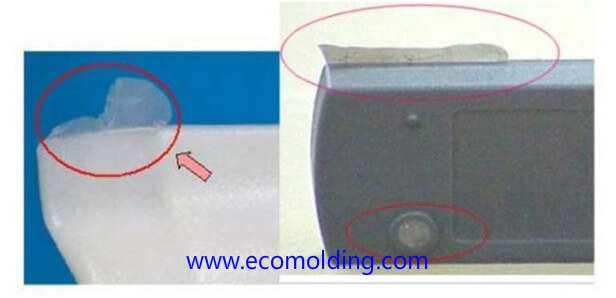
Flash, also known as flashing or burrs, mostly occurs between the matching parts of a mold, such as the parting surface of the mold, the sliding part of the slider, the clearance of the insert, and the gap of the ejector, etc. If the flashing is not resolved in a timely manner, it will be further worsened, so that the mold will be pressed to cause local collapses or other permanent damages. The flashing occurring in the clearance of the insert and the gap of the ejector will also cause the product to stick on the mold, thus affecting ejection.

Flash injection molding defects

Flash is actually the excessive plastic material which enters the matching gaps of the mold and is attached to the final product after cooling. It is very easy to solve the problem of flashing, i.e., keeping the melt out of the matching gaps in a mold. The plastic melt usually enters the mold matching gaps in two scenarios: one is that the mold matching gap is large, making it easy for the melt to get in; the other is that the mold matching gaps are not large at all, but the melt forces its way in due to high pressure. Seemingly, flashing can be completely solved by enhancing the manufacturing precision and the strength of the mold. Surely, it is necessary to improve the manufacturing precision, and reduce the matching clearance of the mold, so as to prevent the molten plastic from entering the gaps. However, the strength of the mold, in many cases, cannot be infinitely strengthened to keep the melt out under any pressure conditions.

The flash problem lies not only in production, but also in the process. To check the process, first check whether the clamping force is sufficient, and only check the mold itself if flashing still occurs after sufficient clamping force is ensured.

Ways to check if the clamping force is sufficient:

1). Gradually increase the injection pressure.  If flashing increases as the pressure goes higher, and the flashing mainly occurs on the mold parting surface, it indicates that the clamping force is insufficient.

2). Gradually increase the clamping force of the injection molding machine. If the flash on the parting surface disappears when the clamping force reaches a certain value, or the flashing on the parting surface no longer worsens when the injection pressure is increased, it is considered that the clamping force is sufficient.

Ways to check if flash is caused by problems lying in mold precision:

Fill the mold cavity just right with a low material temperature, a low injection speed, and a low injection pressure (the product may shrink slightly). At this point of time, it can be considered that the melt is not very likely to enter the mold matching gaps. So, if flashing occurs, it can be determined that the mold manufacturing precision is problematic, thus mold repair is needed. You can give up the idea of solving the flashing issue by looking into the process.

It should be noted that the above-mentioned three “low” conditions are indispensable, as high melt temperature, fast injection speed, and high injection pressure will lead to partial pressure increase in the mold cavity, which may help the melt enter the mold matching gaps. As a result, the mold is forced open, though the cavity is not fully filled at the moment.

The causes of flash are to be analyzed on condition that the clamping force is high enough. If the clamping force is insufficient, it is difficult to analyze the reason for flashing. So, please be aware that the following analysis is based on the assumption that the clamping force is sufficient.

How to improve the life of plastic injection mold?

A plastic injection mold is one of the most important tooling for injection molding, whose quality directly determines the quality of the final product. In the meantime, the mold cost takes up a great proportion in the production cost of an injection molder. If the injection mold life is short and the precision is not well kept, not only will the product quality be affected, but also huge waste will be caused, including material waste and labor waste during plastic injection molding. Therefore, increasing the service life of injection mold has a significant impact on reducing the cost of plastic products, as well as improving tooling productivity and company competitiveness.

injection mold life

During the plastic injection molding process, some plastics will decompose and thus release some corrosive gases under high temperature and high pressure conditions, which causes corrosion and damage to the mold surface. When the mold is damaged, or the shape, dimensional accuracy and surface finish of the plastic part are not up to standard due to the excessive wear of the mold, severe flashing will occur, and if the mold is beyond repair, mold failure will be inevitable. The number of molding cycles or the total number of parts molded before the mold fails is referred to as the service life of a mold. Usually, an injection mold has a service life of more than 300,000 cycles.

Factors that affects the service life of injection molds, and the basic ways to improve the service life

Different injection temperatures and pressures are required for different raw plastic materials, while different working conditions have different effects on the service life of a mold, and different plastic parts also cause different level of tear and wear to the mold. Therefore, under the prerequisite of meeting the product performance and quality requirements, it is usually necessary to select a raw plastic material with great processability to produce the molded product. This is beneficial to both the product molding process and the improvement of the mold service life.

Speaking of mold structural design, the cavity and the core are the main molding parts to shape the plastic products – the cavity shapes the exterior surface of a plastic part, and the core shapes its inner surface. Cavities and cores of different structural designs have different levels of strength and rigidity, thereby different levels of convenience with regard to the repair and replacement of wear parts. Therefore, from the perspective of the service life of a mold, the structural form that is relatively good in strength and rigidity, while being easy to repair is able to extend the service life of a mold.

In addition to the molding parts, other structural parts in a mold should have sufficient strength and rigidity to withstand the mold opening & clamping forces, injection pressure and thermal stress during operation, so as to avoid excessive deformation.

The structure and precision of the guiding mechanism have a direct influence on the clamping of the core and the cavity, which affects the accuracy of the plastic part and the service life of the mold. Therefore, it is necessary to select an appropriate guide form and guide accuracy. Common injection molds mainly rely on the guide pin mechanism to ensure the matching precision. In high-precision injection molds, in order to ensure the matching precision of the mold core and the mold cavity, the tapered precision locating mechanism, or the cylindrical pin locating mechanism and the guide pin can be adopted.

During mold structural design, attention should also be paid to keeping the thermal balance of the mold. The appropriate design of the gating system, the temperature control system and the venting system is able to reduce the hot tearing tendency of the mold, thus improving its service life.

The mold material and the heat-treated injection mold cavity are usually more complicated, with relatively higher requirements for precision and surface roughness. The quality of the mold material influences the quality and service life of the mold. The selection of the mold material must meet the customer’s requirements for the product quality, taking the cost of the material and the strength during the preset period into consideration. During material selection, certain working conditions must be met, such as wear resistance, toughness, thermal resistance, cold / heat fatigue resistance and corrosion resistance.

Whether the heat treatment process is appropriate or not also greatly affects the service life of the mold. The factors affecting the quality of heat treatment include heating rate, quenching temperature, quenching cooling rate and tempering temperature. The heat treatment process should be reasonably carried out during the mold making process, with process conditions strictly controlled.

During the mold making process, the method and accuracy adopted for mold machining and surface finishing have a direct influence on the quality and service life of the mold. If the mold is not appropriately cut, sharp corners or excessively small radius of the fillet will be caused, which may lead to severe stress concentration during mold operation.

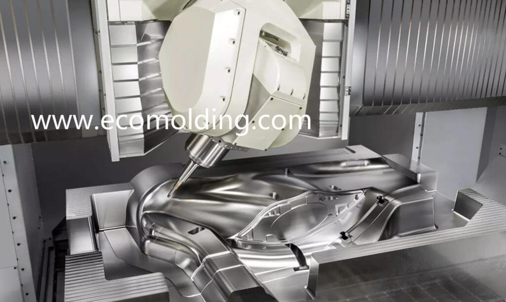
In order to ensure the precision of each part in a mold, high-precision machining methods, such as EDM, wire cutting and CNC should be appropriately selected in the mold making process, in a bid to improve the mold quality and service life.

Whether the mold is appropriately used and maintained is also a major factor affecting the service life. Whether the mold is appropriately set up and commissioned, whether the parameters of the injection molding machine are set in conformity with the design requirements during production, and whether the mold is regularly maintained as planned can all improve the service life of the mold to a certain extent.

Conclusion: The factors that influence the service life of the plastic injection mold are multi-faceted, so comprehensive measures should be taken to improve the service life of them. In the design, manufacturing and application process of the molds, it will help improve the mold quality and service life if you can select the appropriate raw plastic material, reasonably design the mold structure, select the appropriate mold material / heat treatment process / mold machining method, and properly use and maintain the mold.

A Comparison of the HDPE, LDPE and LLDPE Resins

HDPE,LDPE,LLDPE injection molding

This article is to analyze the engineering application scope, the respective characteristics of their applications and the application scope of HDPE, LDPE and LLDPE resin materials from  the aspects of raw material, molecular structure, density, crystallinity, softening point, corrosion resistance, temperature range, mechanical properties, tensile strength, elongation at break, resistance to environmental stress cracking, industrial production principles, processes and additives, etc.

As one of the five commonly used synthetic resins, polyethylene is a synthetic resin that boasts the largest production capacity and the highest import volume in China. At present, China is already the largest importer and the second largest consumer of polyethylene in the whole world. Polyethylene is a mixture of ethylene monomers, while polyethylene plastic is a plastic product made with polyethylene resin as the base material, combined with a small dose of additives, such as antioxidants and slip agents. Polyethylene is mainly divided into three categories: linear low-density polyethylene (LLDPE), low-density polyethylene (LDPE), and high-density polyethylene (HDPE).

1 . High-density polyethylene, abbreviated as HDPE

HDPE is non-toxic, tasteless and odorless, with a density of 0.940 to 0.976 g/cm3. It is produced through low-pressure polymerization with the help of the Ziegler catalyst, so high-density polyethylene is also referred to as low-pressure polyethylene.

HDPE is a thermoplastic resin, which is copolymerized with ethylene to form the high crystallinity and non-polarity properties. The original HDPE has a milky white appearance and a somewhat semi-transparent state in the thin section. It is excellent in resistance to most household and industrial chemicals, able to resist corrosion and dissolution by strong oxidizing agents (concentrated nitric acid), as well as acid / alkali / salt and organic solvents (carbon tetrachloride). The polymer is non-hygroscopic and features a great resistance to water vapor and can be used for moisture-proof and anti-permeability purposes.

Its weakness is that its resistance to aging and environmental stress cracking is not as good as that of LDPE. Especially, its performance will be lowered under the effect of thermal oxidation, so when made into plastic coils, high-density polyethylene is often added with anti-oxidants and UV absorbers to improve the weakness.

2 . Low density polyethylene, abbreviated as LDPE

LDPE is non-toxic, tasteless and odorless, with a density of 0.910 to 0.940 g/cm3. It is produced through polymerization under the 100 to 300MPa high-pressure conditions, by using oxygen or an organic peroxide as the catalyst, so it is also referred to as high-pressure polyethylene.

Low-density polyethylene is the lightest variant among all polyethylene resins. Compared with high-density polyethylene, its crystallinity (55%-65%) and softening point (90-100°C) are relatively lower; it boasts great softness, extensibility, transparency, cold resistance and processability; with an outstanding chemical stability, it is resistant to acid, alkali and salt solutions. Its characteristics also include great electrical insulation and air permeability; low water absorption; and easy combustibility. It is soft in nature and features good elongation, electrical insulation, chemical stability, processability and resistance to low temperature (up to -70°C).

Its weaknesses are its deficiency in mechanical strength, moisture resistance, air permeability and resistance to solvents. The molecular structure is not regular enough, while its crystallinity (55% to 65%) and crystalline melting point (108 to 126°C) is also relatively lower.

Its mechanical strength is lower than that of high-density polyethylene, and its anti-seepage coefficient, thermal resistance and resistance to aging caused by sun exposure are also rather poor. Under sunlight or high temperature conditions, it is prone to aging and discoloration, resulting in performance deterioration, so when made into plastic coils, low-density polyethylene is often added with anti-oxidants and UV absorbers to improve the weaknesses.

3 . Linear Low-density polyethylene, abbreviated as LLDPE

LLDPE is non-toxic, tasteless and odorless, with a density between 0.915 and 0.935 g/cm3. It is a copolymer produced through high-pressure or low-pressure polymerization, using ethylene and a small dose of high-grade α-olefins (such as 1-butene, 1-hexene, 1-octene, 4-methyl-1-pentene, etc.) as the catalysts. The molecular structure of conventional LLDPE is characterized by its linear backbone, with few or no long chain branches, but containing some short chain branches. Without long chain branches, the polymer is endowed with a higher crystallinity.

Compared with LDPE, LLDPE boasts the advantages of higher strength, greater toughness, stronger rigidity, as well as better resistance to heat and cold. In addition, it also features outstanding resistance to environmental stress cracking and tear strength, while being resistant to acids, alkalis and organic solvents.

To sum up, the three above-mention materials play an important role in different types of anti-seepage projects. HDPE, LDPE and LLDPE all boast excellent insulation, moisture resistance and impermeability, and are non-toxic, tasteless and odorless, allowing them to be extremely widely applied in agriculture, aquaculture, artificial lakes, reservoirs and rivers. Therefore, they are vigorously promoted and popularized by the Bureau of Fisheries of the Ministry of Agriculture, the Shanghai Fisheries Research Institute, and the Fishery Machinery and Instrument Research Institute.

In the strong acidic, strong alkaline, strong oxidative and organic solvent environments, the properties of HDPE and LLDPE can be made full use of. Especially, in terms of resistance to strong acid, strong alkali, strong oxidation and organic solvents, HDPE performs far better than the other two materials, so the anti-seepage and anti-corrosion coil materials made from HDPE are widely used in the chemical and environmental protection industries.

Low-density polyethylene also features great resistance to acids, alkalis, and salt solutions, as well as outstanding elongation, electrical insulation, chemical stability, processability, and resistance to low temperature. Therefore, it is widely used in agriculture, aquaculture, packaging (especially low-temperature packaging) and the cable industry.

A Comparison of the Properties of HDPE, LDPE and LLDPE

Plastic Name High-Density Polyethylene Low-Density Polyethylene Linear Low-Density Polyethylene
Property Comparison HDPE LDPE LLDPE
Smell & Toxicity Nontoxic, tasteless and odorless Nontoxic, tasteless and odorless Nontoxic, tasteless and odorless
Density 0.940-0.976g/cm3 0.910-0.940g/cm3  0.915-0.935g/cm3
Crystallinity 85-65% 45-65% 55-65%
Molecular Structure Contains only carbon-carbon and carbon-hydrogen bonds, requiring more energy to break The polymer has a small molecular weight and can be broken with less energy Linear structure with few branch and short chains, can be broken with less energy
Softening Point 125-135℃ 90-100℃ 94-108℃
Mechanical Properties High strength, toughness and rigidity Low mechanical strength High strength, toughness and rigidity
Tensile Strength High Low Higher
Elongation at Break Higher Low High
Impact Strength Higher Low High
Resistance to Moist & Water Good permeability to water, vapor and air; low water absorption; great resistance to seepage Poor airproof and moisture-proof properties Good permeability to water, vapor and air; low water absorption; great resistance to seepage
Resistance to Acid, Alkali, Corrosion and Organic Solvents Resistant to strong oxidants, acids, alkalis and various salts; insoluble in any organic solvents. Resistant to acid, alkali and salt solutions, but with poor resistance to solvents Resistant to acids, alkalis, and organic solvents
Resistance to Heat / Cold Great resistance to heat and cold, even so in the temperature range from room temperature to as low as -40°C; excellent impact resistance; embrittlement temperature < -90°C Low resistance to heat; embrittlement temperature <-70°C Great resistance to heat and cold; embrittlement temperature <-90°C
Resistance to Environmental Stress Cracking Good Better Good

Sink Marks Injection Molding Defects

The dents and hollows on the surface of a plastic product are referred to as “sink marks”. In addition to the appearance of the product, sink marks also affect the quality and strength of the final product. The reasons for sink marks are related to molding processing, mold design and the choice of the plastic material.

sink marks plastic injection molding defects

Raw Material

The shrinkage rates of different plastic materials are different. Usually, the raw materials that are prone to sink marks are crystalline, such as nylon. During the injection molding process, the crystalline plastic is heated to a fluid state, with the molecules randomly arranged; when filled into the cold cavity, the plastic molecules are slowly arranged neatly to crystallize. As a result, the volume is shrunk to be smaller than the specified dimensional range, which is referred to as the “sink mark”.

The shrinkage rates of various plastic materials(mold shrinkage rate) are shown below:

Name of the polymer Explicit name of the polymer Min Value(%) Max Value(%)
ABS Acrylonitrile-Butadiene Styrene 0.7 1.6
ABS FR Acrylonitrile-Butadiene Styrene flame retardant 0.3 0.8
ABS High Heat Acrylonitrile-Butadiene Styrene High Heat 0.4 0.9
ABS High Impact Acrylonitrile-Butadiene Styrene High Impact 0.4 0.9
ABS/PC Acrylonitrile-Butadiene Styrene/Polycarbonate 0.5 0.7
ABS/PC 20% GF Acrylonitrile-Butadiene Styrene/Polycarbonate 20% glass fiber 0.2 0.3
ABS/PC FR Acrylonitrile-Butadiene Styrene/Polycarbonate flame retardant 0.3 0.6
ASA Acrylonitrile Styrene Acrylate 0.4 0.7
ASA/PC Acrylonitrile Styrene Acrylate/Polycarbonate 0.3 0.7
ASA/PC FR Acrylonitrile Styrene Acrylate/Polycarbonate flame retardant 0.4 0.8
ASA/PVC Acrylonitrile Styrene Acrylate/Polyvinyl Chloride 0.3 0.7
CA – Cellulose Acetate Cellulose Acetate 0.3 1
CPVC – Chlorinated Polyvinyl Chloride CPVC – Chlorinated Polyvinyl Chloride 0.3 0.7
EVA Ethylene Vinyl Acetate 0.4 3.5
HDPE – High Density Polyethylene HDPE – High Density Polyethylene 1.5 4
HIPS – High Impact Polystyrene HIPS – High Impact Polystyrene 0.2 0.8
HIPS FR V0 High Impact Polystyrene flame retardant V0 0.3 0.6
LDPE – Low Density Polyethylene LDPE – Low Density Polyethylene 2 4
LLDPE – Linear Low Density Polyethylene LLDPE – Linear Low Density Polyethylene 2 2.5
PA 11 30% Glass fiber reinforced Polyamide 11 30% Glass fiber reinforced 0.5 0.5
PA 11 conductive Polyamide 11 conductive 0.7 2
PA 11 flexible Polyamide 11 flexible 1.4 1.8
PA 11 rigid Polyamide 11 rigid 0.7 2
PA 12 conductive Polyamide 12 conductive 0.7 2
PA 12 fiber reinforced Polyamide 12 fiber reinforced 0.7 2
PA 12 flexible Polyamide 12 flexible 0.7 2
PA 12 glass filled Polyamide 12 glass filled 0.7 2
PA 12 rigid Polyamide 12 rigid 0.7 2
PA 46 Polyamide 46 1.5 2
PA 46 30% GF Polyamide 46 30% glass fiber 0.3 1.3
PA 6 Polyamide 6 0.5 1.5
PA 6-10 Polyamide 6-10 1 1.3
PA 66 Polyamide 6-6 0.7 3
PA 66 30% GF Polyamide 6-6 30% glass fiber 0.5 0.5
PA 66 30% mineral filled Polyamide 6-6 30% mineral filled 0.6 1
PA 66 IM 15-30% GF Polyamide 6-6 impact modified 15-30% glass fiber 0.2 0.6
PA 66 impact modified Polyamide 6-6 impact modified 1.2 3
PBT Polybutylene Terephthalate 0.5 2.2
PBT 30% GF Polybutylene Terephthalate 30% glass fiber 0.2 1
PC 20-40% GF Polycarbonate 20-40% glass fiber 0.1 0.5
PC 20-40% GF FR Polycarbonate 20-40% glass fiber flame retardant 0.1 0.5
PC high heat Polycarbonate high heat 0.7 1
PC/PBT Polycarbonate/Polybutylene Terephthalate blend 0.6 1.1
PCTFE Polymonochlorotrifluoroethylene 0.5 1.5
PE 30% GF Polyethylene 30% glass fiber 0.2 0.6
PEEK Polyetheretherketone 1.2 1.5
PEEK 30% CF Polyetheretherketone 30% carbon fiber 0 0.5
PEEK 30% GF Polyetheretherketone 30% glass fiber 0.4 0.8
PEI Polyetherimide 0.7 0.8
PEI 30% GF Polyetherimide 30% glass fiber 0.2 0.4
PEI mineral filled Polyetherimide mineral filled 0.5 0.7
PEEK– Low cristallinity grade Polyetherketoneketone– Low cristallinity grade 0.004 0.005
PESU Polyethersulfone 0.6 0.7
PESU 10-30% GF Polyethersulfone 10-30% glass fiber 0.2 0.3
PET Polyethylene Terephtalate 0.2 3
PET 30% GF Polyethylene Terephtalate 30% glass fiber 0.2 1
PET 30/35% GF Impact modified Polyethylene Terephtalate 30/35% glass fiber impact modified 0.2 0.9
PET G Polyethylene Terephtalate Glycol 0.2 1
PE-UHMW Polyethylene -Ultra High Molecular Weight 4 4
PMMA Polymethylmethacrylate (Acrylic) 0.2 0.8
PMMA high heat Polymethylmethacrylate (Acrylic) high heat 0.2 0.8
PMMA Impact modified Polymethylmethacrylate (Acrylic) impact modified 0.2 0.8
Polyamide 66 (Nylon 66)/Carbon Fiber, Long, 30 % Filler by Weight Polyamide 66 (Nylon 66)/Carbon Fiber, Long, 30 % Filler by Weight 0.3 0.3
POM Polyoxymethylene (acetal) 1.8 2.5
POM impact modified Polyoxymethylene (acetal) impact modified 1 2.5
POM low friction Polyoxymethylene (acetal) low friction 1.8 3
POM mineral filled Polyoxymethylene (acetal) mineral filled 1.5 2
PP 10-20% GF Polypropylene 10-20% glass fiber 0.3 1
PP 10-40% mineral filled Polypropylene 10-40% mineral filled 0.6 1.4
PP 10-40% TALC Polypropylene 10-40% talc 0.9 1.4
PP 30-40% GF Polypropylene 30-40% glass fiber 0.1 1
PP copo Polypropylene copolymer 2 3
PP homo Polypropylene homopolymer 1 3
PP impact modified Polypropylene impact modified 2 3
PPA Polyphthalamide 1.5 2.2
PPA – 30% mineral Polyphthalamide– 30% mineral 1 1.2
PPA – 33% glass fiber Polyphthalamide – 33% glass fiber 0.5 0.7
PPA – 33% glass fiber – high flow Polyphthalamide– 33% glass fiber – high flow 0.74 0.76
PPA – 45% glass fiber Polyphthalamide– 45% glass fiber 0.1 0.3
PPE Polyphenylene Ether 0.5 0.8
PPE 30% GF Polyphenylene Ether 30% glass fiber 0.1 0.4
PPE FR Polyphenylene Ether flame retardant 0.6 1
PPE impact modified Polyphenylene Ether impact modified 0.6 1
PPE mineral filled Polyphenylene Ether mineral filled 0.3 0.7
PPS Polyphenylene Sulfide 0.6 1.4
PPS 20-30% GF Polyphenylene Sulfide 20-30% glass fiber 0.2 0.5
PPS 40% GF Polyphenylene Sulfide 40% glass fiber 0.2 0.5
PPS conductive Polyphenylene Sulfide conductive 0.3 1
PPS GF & mineral Polyphenylene Sulfide glass fiber & mineral 0.3 0.7
PS 30 % GF Polystyrene 30% glass fiber 0.2 0.2
PS crystal Polystyrene crystal 0.1 0.7
PS high heat Polystyrene high heat 0.2 0.7
PSU Polysulfone 0.7 0.7
PSU 30% GF Polysulfone 30% glass fiber 0.1 0.6
PSU mineral filled Polysulfone mineral filled 0.4 0.5
PVC 20% GF Polyvinyl Chloride 20% glass fiber 0.1 0.2
PVC plasticized Polyvinyl Chloride plasticized 0.2 4
PVC plasticized filled Polyvinyl Chloride plasticized filled 0.8 5
PVC rigid Polyvinyl Chloride rigid 0.1 0.6
SAN Styrene Acrylonitrile 0.3 0.7
SAN 20% GF Styrene Acrylonitrile 20% glass fiber 0.1 0.3

Injection processing:

Regarding control of the injection technology, the causes of sink marks include: insufficient pressure, excessively slow injection speed, small gate or long runner. Therefore, when using the injection molding machine, it is necessary to pay attention to the molding conditions and whether the holding pressure is enough to prevent the appearance of sink marks.

The sink marks on a hard-plastic product are usually caused when the molten plastic shrinks due to cooling, but at the same time sufficient melt is not provided through the gate to fill up the space created by concentrated shrinkage. Therefore, factors that are not conducive to shrinkage compensation will affect our solution for the sink mark issue.

Most people know that it is easy to cause sink marks when the mold temperature is too high. Therefore, they usually prefer to solve the problem by lowering the mold temperature. However, sometimes if the mold temperature is too low, it will not be helpful for solving the problem of sink marks.

When the mold temperature is too low, the melt is cooled very fast. For the thick part that is far away from the gate, sufficient shrinkage compensation will not be possible, since the passage in the middle section is blocked due too fast cooling, thus making it harder to solve the sink mark issue. Sink marks on larger and thicker molded products are particularly serious. Therefore, when dealing with tough sink mark issues, it is helpful to check the mold temperature. Each material has its proper mold temperature.

It is not conducive to solving the sink mark issue when the melt temperature is too low

Similarly, most of us know that a plastic injection molded product is prone to the sink mark issue when the melt temperature is too high. If the temperature can be properly lowered by 10 to 20°C, the sink mark issue will be improved.However, when the injection molded part has a sink mark in a relatively thick part, then setting the melt temperature to a too low level, e.g., close to the lower limit of the melt temperature, will not be helpful for solving the sink mark issue, or even make worse. The thicker the injection molded part, the more obvious it is. PC material is a raw material that solidifies quite quickly, so its sink mark issue can be said to be a big problem in plastic injection molding.Also, if the melt temperature is too low, it will not be conducive to increasing the overall shrinkage amount, resulting in an increase in concentrated shrinkage, thereby exacerbating the sink mark issue.

To solve the sink mark issue, the first thing that comes to mind is to raise the injection pressure and extend the injection time. However, if the injection speed is already very fast, it will not be conducive to solving the sink mark issue. Therefore, when it is difficult to eliminate the sink mark, it should be solved by lowering the injection speed. When the injection speed is lowered, a large temperature difference can be created between the melt front and the gate, which is helpful for melt solidification and shrinkage compensation from the far end to the near, while also allowing the sink mark far away from the gate to get a higher pressure for shrinkage compensation, thus helpful for the problem solving. Due to the lowering of the injection speed, the temperature of the melt front is relatively lower, while the speed has been slowed down, so it is not easy for the molded part to flash. The injection pressure and time can be further increased, to better solve the serious sink mark issues.

Mold & Product Design

The mold runner and cooling designs greatly influence the final product. Due to the low heat transfer capacity of the plastic material, it solidifies and cools slowly. There should be enough plastic to fill the cavities, so that the plastic does not flow back to cause pressure drop when the screw of the injection molding machine is performing injection or pressure holding.

On the other hand, the gate cannot solidify too fast, so that the semi-solid plastic will not block the runner and cause pressure drop, and subsequently sink marks on the product. Different mold flow processes lead to different shrinkage rates. The properly controlled barrel temperature is able to prevent the overheating of the plastic part; extending the cycle is able to allow sufficient time for the product to cool down.

How much does injection molding cost?

The cost of injection molding is influenced by a multitude of factors, but is mainly comprised of the following:

  1. Raw material cost – This cost is quite easy to be calculated. Ask the raw plastic material supplier how much 1kg costs, multiply the product weight by 3% of loss rate, and then multiply the raw material price to get the cost of the raw material;
  2. Machine cost – Regarding this cost, ask a plastic injection molding factory what the hourly processing rates of different plastic injection molding machines are? Assume that the processing cost per hour for a 100-ton plastic injection molding machine is 60 RMB/hour, then the cost per minute is 1 RMB; at this point, it is necessary to calculate the injection molding cycle of the plastic part, as well as the number of cavities of the mold. Assume the injection cycle of the plastic part that you are evaluating is 30 seconds, then there are 60/30 = 2 shots in 1 minute, which means that two rounds of molding can be achieved in 1 minute. And, assume it is a two-cavity mold, then the machine cost of the plastic part is 1 yuan divided by the number of shots in 1 minute, and then divided by the number of cavities in the mold. So, the final machine cost is 1 RMB/ 2 shots / 2 cavities = 0.25 RMB / piece.
  3. The secondary processing cost includes painting/screen printing/electroplating, etc. You may ask their respective processing plants for the figures.
  4. Packaging costs – According to the size and volume of the plastic part, the cost of the carton/bag can be obtained;
  5. Transportation cost – According to the delivery location and the cost of the container truck, the transportation cost per piece can be obtained by dividing the total loading amount;
  6. Other expenses: Because the above costs do not include the costs of indirect personnel or other related personnel, it is necessary to add some fees according to the different conditions of each factory;

The profit equals the total sum of the six items mentioned above multiplied by the profit rate of 10-30%. Then you can get the final cost of a plastic part. The profit should be determined on the basis of the situations in each factory and the order amount.

injection molding cost in china

A Injection mold price calculation method!

Mold price calculation

  1. Empirical calculation of mold price = material fee + design fee + processing fee & profit + VAT + mold trial cost + packaging & transportation fee, of which the percentages are usually:

Material fee: materials and standard parts account for 15%-30% of the total mold price;

Processing fee & profit: 30%-50%;

Design fee: 10%-15% of the total mold price;

Mold trial: for large and medium-sized molds, the cost can be controlled within 3%, and for small-sized precision molds, within 5%;

Packaging & transportation fee: can be calculated in real terms or by 3%;

VAT: 17%

  1. Material coefficient method – The mold material fee can be calculated according to mold size and material price. Mold price = (6~10) * material fee

Plastic mold = 6 * material fee

Die-casting mold = 10 * material fee

Cost accounting for plastic injection molding

Cost of a molded part = material fee + processing fee + packaging fee + transportation fee

Description:

  1. Material fee = [(1 + material loss) * product weight * batch size + material loss during machine adjustment + normal scrap rate * product weight * batch size *] material price / batch size

The material loss is generally 3%-5%; the material loss during machine adjustment and the normal scrapped product usually weigh 5,000g-15,000g.

  1. Processing fee = (machine adjustment time / batch size + molding time / number of mold cavities) * processing cost of the injection molding machine

At present, processing cost of injection molding machine in Shenzhen is calculated by tonnage (domestic equipment)

Tonnage of Machines 80 120 160 200 250 300 400
Cost per hour(RMB) 35-45 65-85 80-110 95-140 150-200 180-220 250-300

Calculation of molded part price – Specifically, the quote for a plastic injection molded part is shown as follows:
Product unit price = material price + processing cost
Material cost = (actual weight + loss) * material unit price
Processing cost = molding cycle * unit price (seconds) ÷ number of cavities (that is, the price of each piece)
If packaging is specifically required, the cost of packaging needs also to be added.
Basically, these are the three major categories.
The material price is relatively simple: PP or ABS is directly calculated as the price * product weight, while that of a colored piece can be calculated on the basis of the raw material price. The price of a black part can be calculated according to the specific recycled materials or product requirements. The processing cost is correlated to the number of mold cavities, the molding cycle and the weight of the product; the machine cost can be detailed to price per second according to machine tonnage. Assume that the number of mold cavities is large, the weight is heavy and the molding cycle is short, the processing cost will be low, accordingly leading to a low unit price.

On assumption that a PP product weighs 50g, make calculations respectively using 1*1 / 1*2 / 1*4. The product is a colored piece made of the new material.cycle time is 60 second.the injection machine is 100 Ton,and cost 60RMB per hour.PP Raw material is 12 RMB per kg.

1*1(1 cavity mold):   

Material cost:0.05×12=0.6RMB ;  processing cost:60/60/1=1RMB; so injection molding price:0.6+1=1.6RMB

1*2(2 cavities mold): 

Material cost:0.05×12=0.6RMB ;  processing cost:60/60/2=0.5RMB; so injection molding price:0.6+0.5=1.1RMB

1*4(4 cavities mold):

Material cost:0.05×12=0.6RMB ; process costing:60/60/4=0.25RMB; so injection molding price:0.6+0.25=0.85RMB

Rapid prototyping play a very important role in China product development

Study shows that 80% of the production cost is determined at the design stage. Therefore, the design stage is of great importance to product cost control. Rapid prototyping constitutes an important part in the industrial design process. From the fully manual prototyping (hand sampling) to the semi-mechanical prototyping, then to the modern 3D printing of prototypes, the progress epitomes the technological progress of the modern manufacturing industry. Among them, though Rapid prototyping is an advanced supportive design technique, it doesn’t receive enough attention.

rapid prototyping in china

It has been proved th Rapid prototyping not only plays a very important role in product design decision, but is also an effective tool for protecting product information and marketing.

Now, let’s talk about the importance of Rapid prototyping from different stages of the industrial design process

  1. Design Optimization

Mechanical parts that are more focused on geometric shapes can be designed directly with the application of computer graphics. For products with curvy surfaces, such as small-sized household appliances, on the one hand, the reverse engineering technology can be leveraged for 3D mapping, to obtain the 3D modeling data. And, after adjustment, the 3D data obtained can be directly copied with the help of the computer-aided rapid prototyping technology. The benefits of this approach are more evident when designing artworks that feature varied curvy designs. Firstly, the designer directly creates the shape with materials such as sludge, and then parameterizes the prototype through a 3D scanning device to obtain the computer data of the original prototype, which is then copied to a rapid prototype, to greatly improve the design efficiency

  1. Design Discussion

During the product design process, discussion plays a very important role. Visualization is an important part in the expression of product design, as well as the cornerstone for design discussion. Modeling products quickly and efficiently is able to ensure a higher design efficiency within the same period of time. During the design creative stage, what is used the most is often the 2D expression based on drawings. However, in the middle and late stages, the design expression will be more specific, so a more intuitive prototype should be adopted as the subject of discussion. Compared with the 2D expression, the hand sample enjoys an irreplaceable advantage, because it is able to make the details of the product clearer and the visual perception of the product more intuitive. Since everyone in the design team is able to see these designs, obvious advantages are demonstrated in the coordination of teamwork among all members.

  1. Functional Test

Rapid prototyping is able to help with certain functional tests and simulate the final form of the product, including functions and curves, etc. Prototyping allows the designer to obtain the most intuitive understanding of the dynamic simulation and internal structure of the prototype. When materials with a certain strength are used, a functional prototype containing an internal structure can be made to verify whether the product structure is reasonable, whether the wall thickness meets the requirements, and whether the moving parts are smooth enough, etc. A prototype can also be used for aerodynamic testing. For example, in the design of fast-moving objects, such as cars, high-speed trains and spacecrafts, a 1:1 prototype can be made and placed into a wind tunnel for intuitive aerodynamics research.

  1. Cost Cut

A design defect that is identified with a CNY 1,000 worth of prototype may cause a huge loss of up to CNY 10 million to produce and test, if the product is put into production and launched into the market. Through hand sampling, the final shape, size, structure and color of the product can be obtained, or product ergonomic testing can be performed at a lower cost. Also, important product information, such as product volume and quality, can be predicted, which can effectively help with the control of the packaging, transportation and material costs during production. Also based on this, the sales price and profit of the product can be estimated. If the cost exceeds the assumptions at the beginning of design, adjustments can be made in a timely manner until the specified target range of cost is reached. Therefore, Rapid prototyping is an effective means for an enterprise to control the cost.

  1. Market Research

In a trade fair, the 2D display board or the 3D animation you show to your potential customers will not be as attractive as the prototype. The prototype can most intuitively indicate the shape, color, size, structure and function of the product. You can also use the rapid hand sampling technology to reproduce the prototypes in small batches, and then send them to different regions for investigation, so as to obtain differentiated survey data. The hand sampling technology is able to help predict the actual consumer mindset and application effects of the product before mass production.

Generally speaking, with the advancement of modern processing technologies, the Rapid prototyping technology is continuously improved with a declined cost. On such a basis, more attention should be paid to the role the rapid prototyping plays in the whole process of industrial design, to make full use of its advantages, thus improving design efficiency and reducing R&D risks.

Benefits of the 3D Printed Prototype:

  • It takes only a few to tens of hours to finish the production of one or several prototypes, so the product development cycle can be reduced by more than 40%;
  • There is no need for mold machining, or mold development. You can print prototypes directly and quickly, to greatly reduce product development costs;
  • Dimensional accuracy is able to meet the requirements of industrial grade assembly. The dimensional accuracy of a plastic sample can reach up to ±0.1mm, while that of a metal sample can reach ±20μm;
  • The plastic sample is made of the high-quality engineering plastic material, the nylon 12, which boasts such excellent properties as high strength, high toughness, as well as high resistance to wear, corrosion and temperature.
  • Rapid prototypes are able to meet a wide range of demanding test requirements, such as wind tunnel testing (3,000rpm), water pressure and flow testing (10,000+ cycles);
  • A variety of complex curves and special structures are available at one stroke.

Different mold cooling channel design cause different cooling effect

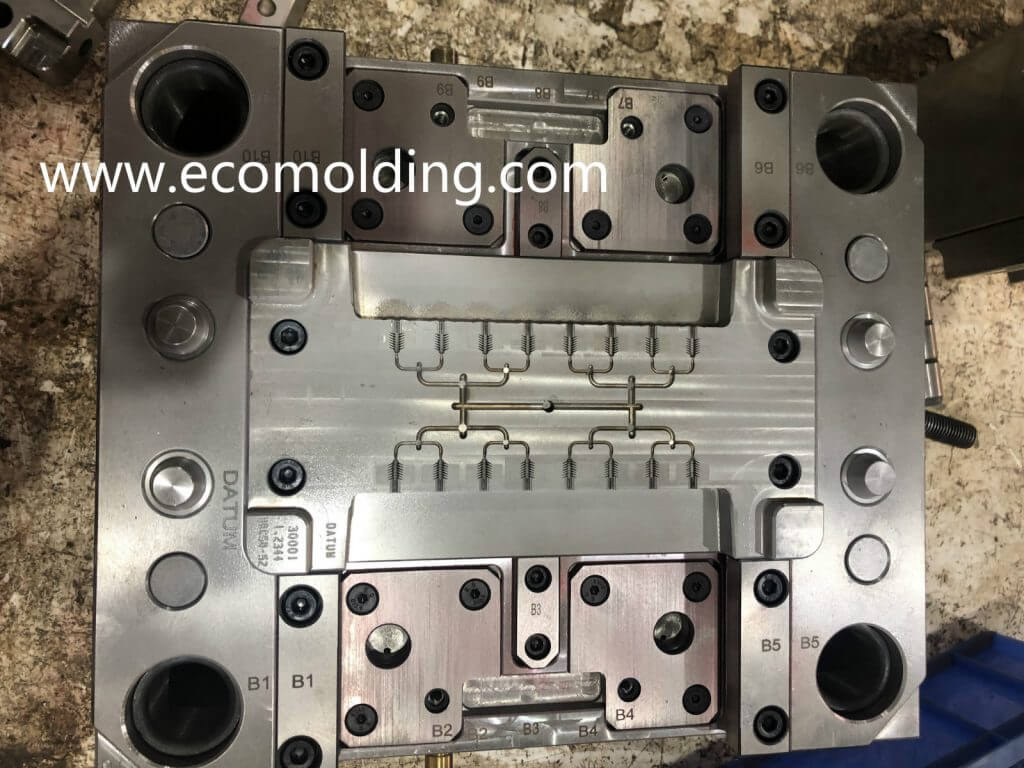
Many believes that the special-shaped cooling channel is not effective at all, but is a kind of deceptive technology! As a matter of fact, the point is not that the special-shaped cooling channel is not effective, but where you choose to place the cooling channel is still arguable. Let’s take a look at the example below:

Figure 1 shows the same part, coming with special-shaped cooling channels designed by different designers. Although all of them adopt the special-shaped design, they perform differently with regard to mold temperature improvement. See Figure 2, let’s verify this using the CAE software. We can find that some of the designs give a great performance as shown in Figure 4, but some others are not so satisfactory as shown in Figure 2. So, what is the problem?

The cooling channel shown in Figure 2 is too densely designed, so when the coolant enters the cavity, it will first take away some of the local heat, not to mention the problem lying in structural strength. At the same time, this amount of heat is kept circulating, which in fact cannot fulfill the function of cooling, but rather heat preservation. The design shown in Figure 4 is able to ensure that the coolant quickly flows to the areas that need to be cooled, while removing the heat from the mold in a fast manner, which is able to accelerate the cooling of the product. Therefore:

  1. The cooling channel needs to be smooth, without any branches, so as to ensure the optimal effect.
  2. It is not right to believe that the more cooling lines and the denser, the better – It is the most important to remove the heat from the mold ASAP.
  3. The shape of the cooling channel also affects the cooling effect.

mold cooling channel

heat emission of mold cooling channel

we have more cooling channel designs,please the below links for detail

Injection Mold Cooling Systems